Table of Contents
Advertisement
Quick Links
General Guide for Installation
- Install the device as far as possible from metal parts and wiring
Altox
harnesses.
- Recommendation: connect device supply directly to the OBD-II connector
wires where pin 16 is +12В, pin 4 is GND (common).
- Auxiliary output OUT commutates at +12V. It is used to start heaters using
an analogous signal and to connect status LED located in the button from
the package, as well as to connect a coolant pump or the interior's heater
via a power relay.
Auxiliary output OUT is switched on with the delay (TIME2 setting) and/or
based on the coolant agent temperature (LTEMP1 setting) after the heater
is switched on. It is switched off with the delay (TIME3 setting) after the
heater is switched off.
- If there are other control units on the bus, it is recommended to connect
the module's control wire (blue) via normally open signaling relay
controlled by output OUT.
In this case you should activate setting SEPARLINE1 that activates this relay
before the data exchange.
O p e r a t i o n a l M a n u a l
- If you need to implement additional options of remote control of output
OUT (for example, to block engine remotely) activate setting SEPAROUT1.
It switches the output mode into manual control mode (SMS-commands:
ACTIVATE / DEACTIVATE).
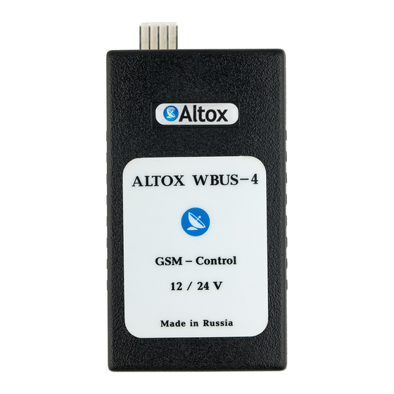
ALTOX WBUS-4 v2
In this mode setting KEEPOUT1 activates option to save and to
subsequently restore of output OUT state when the module's power supply
is switched off and then switched on, respectively.
Please indicate the place of ALTOX module's location in the vehicle for
possible maintenance:
Authorized Service:
Installation Date:
Advertisement
Table of Contents

Summary of Contents for Altox WBUS-4 v2
- Page 1 In this mode setting KEEPOUT1 activates option to save and to subsequently restore of output OUT state when the module's power supply is switched off and then switched on, respectively. Please indicate the place of ALTOX module's location in the vehicle for possible maintenance: Authorized Service:...
- Page 2 Dear buyers of ALTOX equipment! GSM (0-31): 28 - GSM receive signal level (not less than 10) We thank you for purchasing a new ALTOX WBUS-4 v2 device. This device Voltage: 12.8V - car-system voltage will provide you with great options to control your autonomous starting Temp heater: 50С...
- Page 3 PING2:30 The standard ALTOX equipment also includes a button (it is installed if Note: after the setting of the APN point, ALTOX module will switch into required in the car's interior). This button controls the heater and indicates GPRS mode. Internet traffic amounts to less that 3MB not taking rounding its current working status.
- Page 4 To request the account balance of the SIM card (by number from the BAL Technical Settings Command setting) use SMS command «USSD». If you need to request data for another Type of connected heater (see the description above) HEATER-XX phone number, add it in the command: «USSD:*XXX#». Shut off heater when there are errors on digital bus RSTOP1 /0 Additional commands...

Need help?
Do you have a question about the WBUS-4 v2 and is the answer not in the manual?
Questions and answers