Table of Contents
Advertisement
Quick Links
Repair
Electric Airless Sprayers
For portable spray application of architectural paints and coatings. For professional use
only.
Not approved to European explosive atmosphere requirements.
Models
24F562(SP400 Hi Boy)
24F564 (Mustang 4700 Hi Boy)
24F561 (SP400 Stand)
24F563 (Mustang 4700 Stand)
3300 psi (22.7MPa, 227 bar) Maximum Working Pressure
Important Safety Instructions
Read all warnings and instructions in this
manual. Save these instructions.
Related Manuals
3A1180
312363
312365
English
Français Español
312362
312364
SP400 Stand Model 24F561
Mustang 4700 Stand Model 24F563
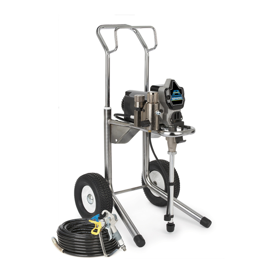
SP400 HiBoy Model 24F562
Mustang 4700 HiBoy Model 24F564
3A1181B
ENG
ti11608a
ti16088a
Advertisement
Table of Contents

Related Manuals for Graco AIRLESSCO SP400 Hi Boy


Summary of Contents for Graco AIRLESSCO SP400 Hi Boy
- Page 1 Repair 3A1181B Electric Airless Sprayers For portable spray application of architectural paints and coatings. For professional use only. Not approved to European explosive atmosphere requirements. Models SP400 Stand Model 24F561 Mustang 4700 Stand Model 24F563 24F562(SP400 Hi Boy) 24F564 (Mustang 4700 Hi Boy) 24F561 (SP400 Stand) 24F563 (Mustang 4700 Stand) 3300 psi (22.7MPa, 227 bar) Maximum Working Pressure...
- Page 2 Warnings Warnings The following warnings are for the setup, use, grounding, maintenance, and repair of this equipment. The exclama- tion point symbol alerts you to a general warning and the hazard symbols refer to procedure-specific risks. When these symbols appear in the body of this manual, refer back to these Warnings. Product-specific hazard symbols and warnings not covered in this section may appear throughout the body of this manual where applicable.
- Page 3 Warnings WARNING WARNING WARNING WARNING FIRE AND EXPLOSION HAZARD Flammable fumes, such as solvent and paint fumes, in work area can ignite or explode. To help prevent fire and explosion: • Do not spray flammable or combustible materials near an open flame or sources of ignition such as cigarettes, motors, and electrical equipment.
- Page 4 Warnings WARNING WARNING WARNING WARNING ELECTRIC SHOCK HAZARD This equipment must be grounded. Improper grounding, setup, or usage of the system can cause electric shock. • Turn off and disconnect power cord before servicing equipment. • Use only grounded electrical outlets. •...
- Page 5 Warnings WARNING WARNING WARNING WARNING EQUIPMENT MISUSE HAZARD Misuse can cause death or serious injury. • Always wear appropriate gloves, eye protection, and a respirator or mask when painting. • Do not operate or spray near children. Keep children away from equipment at all times. •...
-
Page 6: Installation
Installation Installation Grounding and Electric Recommended extension cords: Requirements • 110-120V: 3-wire, 12 AWG (2.5 mm ) minimum. NOTE: Smaller gauge or longer extension cords may reduce sprayer performance. Spray gun: ground through connection to a properly The sprayer cord includes a grounding wire with an grounded fluid hose and pump. -
Page 7: Pressure Relief Procedure
Pressure Relief Procedure Pressure Relief Procedure Follow this Pressure Relief Procedure whenever you 3. Turn prime valve down. are instructed to relieve pressure, stop spraying, check or service equipment or install or clean spray tip. 1. Turn OFF power and turn pressure control to lowest pressure setting. -
Page 8: General Repair Information
General Repair Information General Repair Information NOTICE • Do not run sprayer dry for more than 30 seconds. Doing so could damage pump Flammable materials spilled on hot, bare, motor packings. could cause fire or explosion. To reduce risk of burns, •... -
Page 9: Troubleshooting
Troubleshooting Troubleshooting Problem Cause Solution 1. Pressure control knob setting. Basic Fluid Pressure Slowly increase pressure setting to Motor will not run if set at mini- see if motor starts. mum (fully counter-clockwise). 2. Spray tip or fluid filter may be Relieve pressure, page 7. - Page 10 Troubleshooting Problem Cause Solution 1. Electric supply. ON/OFF switch in Basic Electrical Turn ON/OFF switch to ON position. OFF position. Meter must read See wiring diagram, page 28 Reset building circuit breaker, 100-130 Vac; 210-260 Vac. replace building fuses. Try another outlet.
- Page 11 Troubleshooting Problem Cause Solution 1. Worn spray tip. Low Output Relieve pressure, page 7. Replace tip. Refer to gun instruction manual, 312363. 2. Verify pump does not continue to Service pump. See Displacement stroke when gun trigger is Pump Replacement, page 13. released.
- Page 12 Troubleshooting Problem Cause Solution 1. Prime Valve Open. Motor runs and pump strokes Close prime valve. 2. Paint supply. Refill and reprime pump. 3. Intake strainer clogged. Remove and clean, then reinstall. 4. Suction tube leaking air. Tighten nut. Check o-ring on tube. 5.
-
Page 13: Displacement Pump Replacement
Displacement Pump Replacement Displacement Pump Replacement See manual 312362 for pump repair instructions. 6. Push up retaining spring (C). Push out pump pin (31). Removal 1. Relieve pressure, page 7. Unplug sprayer from outlet. 2. Loosen two screws (11) and remove pail hanger (10). - Page 14 Displacement Pump Replacement Installation 5. Screw in pump until threads are flush with top of drive housing opening. If pump pin works loose, parts could break off due to force of pumping action. Parts could project through air and result in serious injury or property damage. ti6111a NOTICE 6.
-
Page 15: Drive Housing Replacement
Drive Housing Replacement Drive Housing Replacement Removal Installation 1. Relieve pressure, page 7. 1. Apply a liberal coat of grease to gears and needle bearing surfaces. Install thrust bearing (28) and 2. Remove pump (33). Displacement Pump Replace- gears (26) and (27) in motor front endbell. ment, page 13. - Page 16 Spin Test Spin Test 2. If uneven or no resistance, check for missing brush See Wiring Diagrams, page 28. caps, broken brush springs, brush leads, and worn brushes. Repair as needed, page 18. 3. If still uneven or no resistance, replace motor, page To check armature, motor winding and brush electrical continuity: 1.
-
Page 17: Fan Replacement
Fan Replacement Fan Replacement Removal Installation 1. Slide new fan (57a) in place on back of motor. Be sure blades of fan face motor as shown. 2. Install spring clip (57b). 1. Relieve Pressure, page 7. Disconnect power cord 3. Replace shroud (12) and two screws (4). from outlet. -
Page 18: Motor Brush Replacement
Motor Brush Replacement Motor Brush Replacement See Wiring Diagram, page 28. the brush lead. You will hear a snap when cap is securely in place. Removal 3. Strip approximately 1/4 inch (6 mm) of insulation Replace brushes worn to less than 1/4 in. (6 mm). from end of each yellow wire (C) from motor. -
Page 19: Control Board Replacement
Control Board Replacement Control Board Replacement See Wiring Diagram, page 28. Removal 7. Pull control board out slightly and then slide control board back and off of frame. 1. Relieve pressure, page 7. Disconnect power cord from outlet. NOTE: Make sure power cord is free and not wrapped around cord wrap. - Page 20 Control Board Replacement Installation 1. Push grommet and power cord wires into strain 3. Slide control board into place on side of motor front relief in control board (18). endbell. Strain Relief Grommet ti6122a 2. Connect power cord connectors to terminals indi- cated on control board (18).
-
Page 21: Fuse Replacement
Fuse Replacement Fuse Replacement If the fuse is blown, check for: Removal 1. Relieve pressure, page 7. Disconnect power cord • Pinched or shorted wires from outlet. • A defective motor (see Spin Test, page 16) 2. Hi-Boy Models Only - Disconnect high-pressure hose at pump outlet (see page 13). -
Page 22: Pressure Control Assembly Replacement
Pressure Control Assembly Replacement Pressure Control Assembly Replacement See Wiring Diagram, page 28. Removal 1. Relieve pressure, page 7. Disconnect power cord 7. Loosen and unscrew pressure control. from outlet. 2. Hi-Boy Models Only - Disconnect high-pressure hose at pump outlet (see page 13). 3. - Page 23 Pressure Control Assembly Replacement Installation 3. Apply loctite to pressure control knob (B) threads. 4. Screw pressure control threads (B) into manifold and torque to 150 in-lb (17.0 N.m). NOTE: Be careful when tightening pressure control knob that wires are not pinched between pressure con- trol and fluid manifold.
-
Page 24: Drain Valve Replacement
Drain Valve Replacement Drain Valve Replacement Removal Installation 1. Relieve pressure, page 7. Disconnect power cord 1. Install new seat gasket (44a) and valve seat (44b) from outlet. on end of drain valve. 2. Remove pin (47) from drain valve handle (46). 2. -
Page 25: Drain Line Replacement
Drain Line Replacement Drain Line Replacement Removal Installation 1. Cut drain line (49) from barbed fitting (51). 1. Screw barbed fitting (51) into filter manifold (43). 2. Unscrew barbed fitting from filter manifold (43). 2. Push drain line (49) onto barbed fitting. NOTE: To reuse existing barbed fitting (51) and drain NOTE: To make drain line more pliable and easier to line (49), cut and remove remaining drain line material... -
Page 26: Power Cord Replacement
Power Cord Replacement Power Cord Replacement Installation See Wiring Diagram, page 28. 1. Connect green ground wire (G) to frame with green ground screw (20). Be sure green ground wire ter- minal faces up or wires could get caught in shroud. 2. -
Page 27: Motor Replacement
Motor Replacement Motor Replacement 6. Remove two screws (4) and filter manifold (43). See Wiring Diagram, page 28. 7. Remove green ground screw (20) and ground wire (G) from motor endbell. 8. Remove cover (14). Remove four screws (4) and motor (57) from frame (1). -
Page 28: Wiring Diagrams
Wiring Diagrams Wiring Diagrams 120V from Motor Red (+) 2 x Yellow Black (-) Replaceable Fuse Pressure Control Assembly ON/OFF Switch ti5643a Black Capacitor Power White Plug Green ti5643a1 3A1181B... - Page 29 Notes Notes 3A1181B...
- Page 30 Parts (Stand) Parts (Stand) Models 24F561, 24F563 • ti10332a 3A1181B...
- Page 31 Parts List (Stand) Models 24F561, 24F563 Parts List (Stand) Models 24F561, 24F563 Ref Part Description Ref Part Description 162453 FITTING, (1/4 npsm x 1/4 npt) 15E823 FRAME, stand mount 246385 STRAINER, 7/8-14 unf 116139 GRIP, handle 114958 STRAP, tie 119723 TAPE, foam 246386 HOSE, suction set, includes 41, 40,...
- Page 32 Parts (Stand) Models 24F561, 24F563 Parts (Stand) Models 24F561, 24F563 • • • • ti10331a 3A1181B...
- Page 33 Parts (Stand) Models 24F561, 24F563 Parts List (Stand) Models 24F561, 24F563 Part Description Part Description 224807 BASE, valve 117493 SCREW, mach, hex washer hd 187625 HANDLE, valve, drain 117501 SCREW, machine, hex washer 111600 PIN, grooved head 195811 LABEL, instruction 249005 CONTROL, pressure, includes 21, 23, 03...
- Page 34 Parts (Hi-Boy) Models 24F562, 24F564 Parts (Hi-Boy) Models 24F562, 24F564 • ti10336b 3A1181B...
- Page 35 Parts List (Hi-Boy) Models 24F562, 24F564 Parts List (Hi-Boy) Models 24F562, 24F564 Part Description Part Description 288216 FRAME, cart, hi 195150 NUT, jam, pump 245245 HANDLE, cart 162453 FITTING, (1/4 npsm x 1/4 npt) 117493 SCREW, mach, hex washer hd 235004 STRAINER, 3/4-16 unf 109032...
- Page 36 Parts List (Hi-Boy) Models 24F562, 24F564 Parts (Hi-Boy) Models 24F562, 24F564 • • • • 3A1181B...
- Page 37 Parts List (Hi-Boy) Models 24F562, 24F564 Parts List (Hi-Boy) Models 24F562, 24F564 Part Description Part Description 195811 LABEL, instruction 117493 SCREW, mach, hex washer hd 15K092 TUBE, drain 117501 SCREW, mach, slot hex wash hd 244035 DEFLECTOR, barbed 249005 CONTROL, pressure M70809 FITTING, barbed, hose (includes 21, 22, 23) 104361...
-
Page 38: Technical Data
Technical Data Technical Data Power requirements ........100/120V AC, 50/60 hz, 11A, 1 phase Generator required. - Page 39 Notes Notes 3A1181B...
-
Page 40: Airlessco Standard Warranty
Airlessco Standard Warranty Airlessco warrants all equipment referenced in this document which is manufactured by Airlessco and bearing its name to be free from defects in material and workmanship on the date of sale to the original purchaser for use. With the exception of any special, extended, or limited warranty published by Airlessco, Airlessco will, for a period of twelve months from the date of sale, repair or replace any part of the equipment determined by Airlessco to be defective.
Need help?
Do you have a question about the AIRLESSCO SP400 Hi Boy and is the answer not in the manual?
Questions and answers