
Related Manuals for Encoder A58HE

Summary of Contents for Encoder A58HE
- Page 1 M a n u a l for encoder products Company Absolute profinet encoders 1-800-366-5412 • encoder.com...
- Page 2 M a n u a l ©2019 Encoder Products Company. All rights reserved. 464276 Highway 95 South...
-
Page 3: Table Of Contents
5.2.3 Versions ..................25 1.4 Scope of Delivery ................... 3 5.3 Configuration ..................26 5.3.1 Network ..................26 2 Safety Information ..............3 5.3.2 Encoder ..................27 2.1 General ..................3 5.3.3 Firmware Update ............... 27 2.2 Intended Use ..................3 5.4 License information ................ - Page 4 M a n u a l Index of Figures Figure 3.1: A58HE/SE with PROFINET-IRT Bus Cover ..... 4 Figure 5.1: Web server – Overview..........23 Figure 5.2: Diagnostic Page ............24 Figure 5.3: Versions ..............
- Page 5 p r o f i n e t i n t e r f a c e t e c h n i c a l r e f e r e n c e M a n u a l Index of Figures Figure 6.24: Example of Commissioning ........
- Page 6 p r o f i n e t i n t e r f a c e t e c h n i c a l r e f e r e n c e M a n u a l Index of Tables Table 3.1: Pin Connection Assignment ................
-
Page 7: Introduction
1.1 About This Manual This technical manual describes the configuration and mounting possibilities for absolute-value encoders with a PROFINET interface produced by Encoder Products Company (EPC). It supplements the other publicly available EPC documents, e.g. data sheets, assembly instructions, leaflets, catalogues and flyers. -
Page 8: 1.1.2 What Is Not In This Manual
Patented technologies for single-turn and for multi-turn are used in the A58SE and A58HE series encoders. As a result, these encoders from EPC are maintenance-free and very eco-friendly. -
Page 9: Scope Of Delivery
EMC and Machine Directive. A rotary encoder is a sensor that is designed to detect angular positions and revolutions and must only be used for this purpose! EPC Automation manufactures and distributes encoders for use in non-safety-relevant industrial applications. -
Page 10: Safe Working
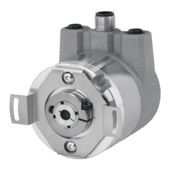
Figure 3.1: EPC EtherCAT-Ready Encoders with PROFINET-IRT Bus Covers From left to right: A58SE with clamping flange; A58SE with synchro flange; A58SE heavy-duty; A58SE compact; A58HE (blind hollow bore) EPC Technical Reference Manual 1-800-366-5412 • encoder.com • sales@encoder.com... -
Page 11: Profinet
3.3.1 Single Turn – ST Measurement of the angle from 0° to 360° by means of a shaft represents the minimum functionality of a rotary encoder. The sensor system is based on optical or magnetic sampling of a measuring graduation on the encoder shaft. -
Page 12: 3.3.2 Multi-Turn - Mt
3.3.2 Multi-Turn – MT A multi-turn encoder allows the number of revolutions to be recorded. This is achieved via a rotation counter. The A58SE and A58HE encoders include technology, which ensures that the corresponding information is retained, even in a voltage- free state. -
Page 13: 3.4 Connection Assignments For Profinet Encoders
Bus Cover with 3 x M12x1 The "RNB" code in the order key refers to an encoder with a bus cover. The electrical connection is made at the bus cover via the 2 x M12 plugs and 1 x M12 socket. The connection assignment of the plugs and sockets can be found in Table 3.1. -
Page 14: Leds And Signalling
M a n u a l LEDs and Signalling Four status LEDs on the bus cover signal the various encoder states and thus support error diagnosis and troubleshooting in the field (see Table 3.2). The two Link Activity LEDs (L/A) light up or flash green when the encoder is connected to another PROFINET node (PLC, switch, additional field device...) and data is being exchanged. The STAT LED indicates the status of the fieldbus, the MOD LED the status of the encoder. STAT LED MOD LED Meaning Cause... -
Page 15: Mac Address And Ip Address
EPC PROFINET encoders have three MAC addresses. These always start with D4-90-E0-xx-xx-xx. The number depends on the number of ports on the integrated three-port switch. There is one MAC address each for Port1 and Port2, as well as one MAC address for the "internal port" to which the encoder itself is connected. In the delivered state, the PROFINET encoder has no IP address and no name. These are defined during configuration (e.g., TIA Portal). -
Page 16: Profinet
Multi-turn 16 bit + single-turn 16 bit = 32 bits in total MT3916 Multi-turn 39 bit + single-turn 16 bit = 55 bits in total Table 4.2: GSDML Modules EPC Technical Reference Manual 1-800-366-5412 • encoder.com • sales@encoder.com Absolute Encoders with PROFINET Interface Page 10 of 55 REV. 10/01/19... -
Page 17: Signals
Right-aligned, output in set unit Velocity value A 15 … 0 (see Table 4.18, Velocity Measuring Units) Table 4.4: Structure of signal 6 NIST_A EPC Technical Reference Manual 1-800-366-5412 • encoder.com • sales@encoder.com Absolute Encoders with PROFINET Interface Page 11 of 55 REV. 10/01/19... -
Page 18: Table 4.5: Structure Of Signal 8 Nist_B
10 ... 0 Reserved, currently not used Table 4.6: Structure of signal 9 G1_STW To enable the encoder to respond to the requirements in G1_STW, the controller must set bit 10 to 1 in STW2_ENC. EPC Technical Reference Manual 1-800-366-5412 • encoder.com • sales@encoder.com... -
Page 19: Table 4.7: Structure Of Signal 10 G1_Zsw
Absolute position value 1 31 ... 0 Right-aligned Table 4.8: Structure of signal 11 G1_XIST1 Structure of G1_XIST1 using the example of a 16-bit multi-turn and a 16-bit single-turn encoder: M = multi-turn / S = single turn This value includes the position, has a width of 32 bits, and is unsigned. The encoder parameter settings influence this position value if "Class 4 functionality" is activated. The influence of the preset functionality can be controlled with "G1_XIST1 Preset Control". -
Page 20: Table 4.9: Structure Of Signal 12 G1_Xist2
This value includes the position, has a width of 64 bits and is unsigned. It can be used if the measuring range of the encoder is larger than 32 bits. The encoder parameter settings influence this position value if "Class 4 functionality" is activated. EPC Technical Reference Manual 1-800-366-5412 • encoder.com • sales@encoder.com Absolute Encoders with PROFINET Interface Page 14 of 55 REV. 10/01/19... -
Page 21: Table 4.11: Structure Of Signal 80 Stw2_Enc
M a n u a l STW2_ENC: Encoder control word 2... -
Page 22: Table 4.13: Structure Of Signal 238(60000) G1_Xist1_Preset_A
15 ... 1 Not used Test error active Indicates that the test error is set Table 4.15: Structure of signal 60002 DEBUG_ZSW EPC Technical Reference Manual 1-800-366-5412 • encoder.com • sales@encoder.com Absolute Encoders with PROFINET Interface Page 16 of 55 REV. 10/01/19... -
Page 23: Telegrams
ENC-> SPS G1_XIST1 NIST_B STW2_ DEBUG SPS-> ENC _STW 59000 ZSW2_ DEBUG ENC-> SPS G1_XIST1 G1_XIST2 _ZSW Table 4.16: Telegrams EPC Technical Reference Manual 1-800-366-5412 • encoder.com • sales@encoder.com Absolute Encoders with PROFINET Interface Page 17 of 55 REV. 10/01/19... -
Page 24: Parameters
2000 Hysteresis position 2002 Extrapolation position 2003 Filter max. RPM 2004 Filter position 2005 Filter speed Table 4.17: Supported parameters EPC Technical Reference Manual 1-800-366-5412 • encoder.com • sales@encoder.com Absolute Encoders with PROFINET Interface Page 18 of 55 REV. 10/01/19... -
Page 25: 4.6.1 Description Of The Most Important Parameters
Setting a preset value has no effect on the position value for the time being. The preset function is only executed by setting bit 12 in G1_STW. EPC Technical Reference Manual 1-800-366-5412 • encoder.com • sales@encoder.com Absolute Encoders with PROFINET Interface Page 19 of 55... -
Page 26: Table 4.18: Velocity Measuring Units
The offset value is calculated during execution of the preset and is then added to the position value. It is stored in non-volatile memory and can be read by the encoder at any time. The offset value can assume values within the scaled measurement range 4.6.1.10 Hysteresis position... -
Page 27: Table 4.20: Extrapolation Position
Unsigned 8 Access Values 0 … 255 Default Explanation Number of average values for the position value Table 4.22: Filter position EPC Technical Reference Manual 1-800-366-5412 • encoder.com • sales@encoder.com Absolute Encoders with PROFINET Interface Page 21 of 55 REV. 10/01/19... -
Page 28: Warnings And Errors
All have invalid position values 0x0F01 Command not supported – – 0x0F02 PLC sign-of-life error 0X0F04 Synchronisation error Table 4.26: G1_XIST2 error codes EPC Technical Reference Manual 1-800-366-5412 • encoder.com • sales@encoder.com Absolute Encoders with PROFINET Interface Page 22 of 55 REV. 10/01/19... -
Page 29: Web Server
IP address into a browser of your choice (Internet Explorer, Firefox, etc.). To do so, connect the encoder to your com- puter using an Ethernet cable (M12 connector on the encoder and RJ45 connector on the PC). Ensure that your PC is in the same IP address range as the encoder. -
Page 30: Diagnosis
You can change the language of the web server after accessing it. After switching inside a sub-screen, the web server restarts from the start screen. 5.2.2 Diagnosis Figure 5.2: Diagnostic page EPC Technical Reference Manual 1-800-366-5412 • encoder.com • sales@encoder.com Absolute Encoders with PROFINET Interface Page 24 of 55 REV. 10/01/19... -
Page 31: Versions
Possible causes of errors are displayed here. If you see an error here, please either contact us or refer to the manual for possible causes. Fieldbus • CPU Load: this shows the CPU utilisation of the encoder during operation. • Interface: ▪ Type: the protocol is displayed here; Ethernet ▪ State: the mode is specified here. Only static IP is specified. DHCP mode is not possible. -
Page 32: 5.3 Configuration
Figure 5.4: Network settings You can change the device name, IP address, network mask and gateway here. Please note that this data should only be modified when the system is not in operation. EPC Technical Reference Manual 1-800-366-5412 • encoder.com • sales@encoder.com Absolute Encoders with PROFINET Interface Page 26 of 55 REV. 10/01/19... -
Page 33: Encoder
Please note that the firmware must only be updated when the system is not in operation. • Do not cut off the power supply or disconnect the network cable while performing a firmware update. To update the firmware of the encoder, choose the correct .bin file by clicking the “Browse…”-Button (see Figure 5.7: Firmware update - choose file). EPC Technical Reference Manual 1-800-366-5412 • encoder.com • sales@encoder.com Absolute Encoders with PROFINET Interface Page 27 of 55 REV. 10/01/19... -
Page 34: Figure 5.7: Firmware Update - Choose File
M a n u a l 5.7: Firmware update - choose file After you have chosen the correct file, click the “Update”- Button to start the firmware update. An animated icon will appear with the additional text: “Transferring file” (see Figure 5.8). Figure 5.8: Firmware update - Transferring file After the firmware update is successfully finished, you will see it on the website like in Figure 5.9. Perform a power reset and check under “Information -> Versions” to confirm that the new firmware version is shown. EPC Technical Reference Manual 1-800-366-5412 • encoder.com • sales@encoder.com Absolute Encoders with PROFINET Interface Page 28 of 55 REV. 10/01/19... -
Page 35: Figure 5.9: Firmware Update - Successful
If this happens, please contact our support team. Figure 5.10: Firmware update - Failed EPC Technical Reference Manual 1-800-366-5412 • encoder.com • sales@encoder.com Absolute Encoders with PROFINET Interface Page 29 of 55 REV. 10/01/19... -
Page 36: License Information
Contact Figure 5.12: Contact information Contact information for additional product information and technical support is listed here. EPC Technical Reference Manual 1-800-366-5412 • encoder.com • sales@encoder.com Absolute Encoders with PROFINET Interface Page 30 of 55 REV. 10/01/19... -
Page 37: Commissioning
Connect the encoder to your controller. Connect the encoder's power supply. To integrate the encoder into your TIA portal project, start your TIA portal, open the required project and switch to the project view by pressing the "Project view" button (see Figure 6.1). -
Page 38: Figure 6.2: Manage Device Description File (Gsd)
The corresponding .bmp file must be located in the same directory as the GSDML file during installation and is included in the download. Figure 6.2: Manage device description file (GSD) Now select the path for the GSDML file, activate the checkmark next to the desired GSDML file and confirm the installation via the "Install" button (see Figure 6.3). Then close the installation window. EPC Technical Reference Manual 1-800-366-5412 • encoder.com • sales@encoder.com Absolute Encoders with PROFINET Interface Page 32 of 55 REV. 10/01/19... -
Page 39: Figure 6.3: Installing Gsdml
From the "Project tree" column on the left of the TIA portal, select the "Devices & networks" tab (see Figure 6.4). The hardware view opens and the hardware catalogue is now visible in the right-hand column. Figure 6.4: Switch to Devices & Networks EPC Technical Reference Manual 1-800-366-5412 • encoder.com • sales@encoder.com Absolute Encoders with PROFINET Interface Page 33 of 55 REV. 10/01/19... -
Page 40: Figure 6.5: Hardware Catalogue
Now "drag" the encoder onto the "PROFINET IO system". This encoder is now displayed in the hardware view. Connect the encoder to the controller by dragging the encoder port onto the appropriate controller port. The result is shown in Figure 6.6. -
Page 41: Figure 6.8: Select Module
Now select the desired telegram for communication. To do so, proceed as in the previous step. Select "Slot 1 2". The various telegrams can be found under "Profile" in the "Submodules" tab (see Figure 6.9). Figure 6.9: Select telegram EPC Technical Reference Manual 1-800-366-5412 • encoder.com • sales@encoder.com Absolute Encoders with PROFINET Interface Page 35 of 55 REV. 10/01/19... -
Page 42: Figure 6.10: Change The I/O Addresses
M a n u a l You can also set the corresponding I/O addresses. To do so, double-click on the respective field and change the address (see Figure 6.10). Figure 6.10: Change the I/O addresses Click on your PLC in the project navigation window and load the configuration by clicking the "Download to device" button (see Figure 6.11). Figure 6.11: Download to device EPC Technical Reference Manual 1-800-366-5412 • encoder.com • sales@encoder.com Absolute Encoders with PROFINET Interface Page 36 of 55 REV. 10/01/19... -
Page 43: Figure 6.12: Assigning Device Names
(see Figure 6.12). Figure 6.12: Assigning device names Assign a name to the encoder. Then select your PG/PC interface and the type and click on "Update list" (see Figure 6.13) Figure 6.13: Name and PG interface EPC Technical Reference Manual 1-800-366-5412 •... -
Page 44: Figure 6.14: Accessible Nodes
M a n u a l All devices are now displayed under "Accessible devices in the network". Select your encoder and click on "Assign name"... -
Page 45: Figure 6.15: Online Status Information
You will now see the successfully assigned name in the online status information. Click on "close" (see Figure 6.15). Figure 6.15: Online status information EPC Technical Reference Manual 1-800-366-5412 • encoder.com • sales@encoder.com Absolute Encoders with PROFINET Interface Page 39 of 55... -
Page 46: Figure 6.16: Plc Variables
M a n u a l You can use a variable table to display the encoder's I/O data for test purposes. To do so, open the default tag table (see Figure 6.16) and enter the corresponding address for the position value. -
Page 47: Scaling Function
M a n u a l Scaling function In order to set a different number of steps / revolutions or revolutions than the one given in the GSDML file, the scaling function must be activated. The following two examples explain this for a single-turn and a multi-turn encoder. It is assumed that you have already configured the encoder and your PLC in the TIA portal. 6.3.1 Example scaling function single-turn 16-bit to 12-bit Double-click on the image of the encoder in the network view of "Devices and Networks". -
Page 48: Figure 6.20: Device Overview - Map
The "Assembly parameters" which we click on will then appear in the "Properties" under "Device overview" in the "General" tab. (see Figure 6.21). Figure 6.21: Assembly parameters EPC Technical Reference Manual 1-800-366-5412 • encoder.com • sales@encoder.com Absolute Encoders with PROFINET Interface Page 42 of 55 REV. 10/01/19... -
Page 49: Figure 6.22: Default Assembly Parameters 16-Bit Single-Turn
M a n u a l The default settings of the 16-bit single-turn encoder are shown in Figure 6.22. -
Page 50: 6.3.2 Example Scaling Function Multi-Turn
M a n u a l 6.3.2 Example scaling function multi-turn Double-click on the image of the encoder in the network view of "Devices and Networks". (see Figure 6.24) Figure 6.24: Example of commissioning... -
Page 51: Figure 6.26: Assembly Parameters
The "Assembly parameters" which we click on will then appear in the "Properties" under "Device overview" in the "General" tab (see Figure 6.26). Here you can also see the default settings of a 43-bit multi-turn and 16-bit single-turn encoder. Figure 6.26: Assembly parameters In this example we want to set a resolution of 360 steps/revolution and 10 countable revolutions (10 x 360 steps = 3600 steps total resolution). -
Page 52: Executing A Preset
I8..I11 Table 6.1: Data content for Example Set the encoder to normal, controlled operation during start-up or manually via an observation table. To do this, set STW2_ENC bit 10 "Control by PLC" to TRUE. Figure 6.28: set STW2_ENC bit 10 to TRUE EPC Technical Reference Manual 1-800-366-5412 •... -
Page 53: Figure 6.29: Set G1_Stw Bit 13 To True
Figure 6.30: G1_STW Bit 11 default 0 = absolute The preset to the pre-defined preset value (0 by default, adjustable via PNU 65000 or PNU 65002) can now be executed with a pulse to G1_STW Bit 12 "Request of home position" (set and reset). EPC Technical Reference Manual 1-800-366-5412 • encoder.com • sales@encoder.com Absolute Encoders with PROFINET Interface Page 47 of 55 REV. 10/01/19... -
Page 54: Resetting A Preset
This ensures that an offset value is not used that may not match the set scaling. The preset is executed by the encoder on a rising edge to G1_STW bit 12; it is confirmed on the following falling edge. Only then the preset can be executed again. -
Page 55: Integration Into A Step 7 Project
Integration into a Step 7 project Connect the encoder to your controller. Connect the encoder's power supply. To integrate the encoder into your SIMATIC Manager project, double-click the "Hardware" button to start the hardware configuration tool (see Figure 6.32). Figure 6.32: SIMATIC Manager Next, install the GSDML file. You can download this from www.encoder.com. To do so, open the "Extras" tab and select "Install GSD file" (see Figure 6.33). -
Page 56: Figure 6.33: Installing The Gsdml File
Figure 6.33: Installing the GSDML file Now select the path for the GSDML file, select the desired GSDML file and confirm the installation via the "Install" button. Then close the installation window. Add the encoder to your hardware configuration. To do so, open the following path at the right edge of the screen (see Figure 6.34): "PROFINET IO/Additional Field Devices/Encoders/Encoders Product Company/Absolute Encoder/EPC Encoder". Figure 6.34: Hardware catalogue EPC Technical Reference Manual 1-800-366-5412 • encoder.com • sales@encoder.com Absolute Encoders with PROFINET Interface Page 50 of 55 REV. -
Page 57: Figure 6.35: Hardware View
M a n u a l Now "drag" the encoder onto the "PROFINET IO system". The encoder is then displayed in the hardware view (see Figure 6.35). Enter a meaningful device name for the configured encoder by double-clicking the encoder symbol. -
Page 58: Figure 6.37: Select The Properties And The Telegram
Figure 6.39: Slot 1.2 with inserted telegram 81 You can also set the corresponding I/O addresses. To do so, double-click on the respective field (see Figure 6.40) and change the addresses in the "Addresses" tab (see Figure 6.41). Figure 6.40: Change the I/O addresses EPC Technical Reference Manual 1-800-366-5412 • encoder.com • sales@encoder.com Absolute Encoders with PROFINET Interface Page 52 of 55 REV. 10/01/19... -
Page 59: Figure 6.41: "Addresses" Tab
Figure 6.41: "Addresses" tab Save the configuration by clicking the "Save and transmit" button and load it into your PLC ("Download to module"). Figure 6.42: Save and transmit – Download to module You can use a variable table to display the encoder's I/O data for test purposes (see Figure 6.43 and Figure 6.44). Figure 6.43: Variable table EPC Technical Reference Manual 1-800-366-5412 •... -
Page 60: Figure 6.44: Hex Position Value
M a n u a l Figure 6.44: HEX position value EPC Technical Reference Manual 1-800-366-5412 • encoder.com • sales@encoder.com Absolute Encoders with PROFINET Interface Page 54 of 55... -
Page 61: Technical Data
Aluminium Housing Flange material (rear): Steel housing, chromium-plated, magnetically shielded Connection hood: Die-cast aluminium, powder-coated Dimensions For product dimensions, please see the appropriate product drawings at encoder.com/products. Technical support Do you have any questions about this product? Our technical application support engineers will be happy to help you. Tel.: +1 208 263 8541 Fax: +1 208 263 0541 E-mail: support-epcmag@encoder.com... - Page 62 M a n u a l Figure 6.14: Contact Information EPC Technical Reference Manual 1-800-366-5412 • encoder.com • sales@encoder.com Absolute Encoders with PROFINET Interface Page 56 of 55...
Need help?
Do you have a question about the A58HE and is the answer not in the manual?
Questions and answers