Advertisement
Quick Links
GIGABIT
PoE
Injector
Q
I
uick
nstallation
I N D U S T R I A L
Introduction
The
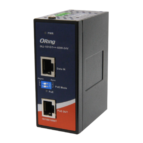
INJ-101GT++ PoE Injector series
device but also an advanced high power PoE injector. It is intelligent
detection that provided 1-ports 10/100/1000Base-T (X) PoE outputs. The
device does not turn on power until it detects a valid PoE signature from the
PoE devices attached downstream on the Ethernet cable. This protection
against damage to non-PoE compliant equipment which may be connected to
the Ethernet cable. Therefore, only an IEEE 802.3at/802.3af compliant
device can be powered with the
INJ-101GT++
Gigabit networks the maximum allowable CAT5 cable length is about 100
meters, due to the limitation of the Ethernet standards. The INJ-101GT++
PoE Injector can function with any PoE P.D. equipment which is fully
compliant with the IEEE 802.3af/at PoE standards, and provide the DIP
switch configurator for High power PoE management.
Features
PoE++ Injector for 1x10/100/1000Base-T(X)
Fully compliant with IEEE802.3at/802.3af standard
Auto protection for Over Voltage Power Input and over current output
Supports totally Power Output up to 100 Watts
Support wide range power input, 12 to 57VDC (-24V Model Only)
Provided DIP switch configurator for PoE mode management
High reliability and rigid IP-30 housing
DIN-Rail and wall-mount enabled
Package Contents
The device is shipped with the following items. If any of these items is
missing or damaged, please contact your customer service representative
for assistance.
Contents
Pictures
INJ-101GT++-100W or
INJ-101GT++-100W-24V
QIG
For INJ-102GT++
25mm DIN-rail kit
Wall-Mount Kit
For INJ-102GT++-24V
40mm DIN-rail kit
Wall-Mount Kit
Q I G
INJ-101GT++-100W Series
INJ-101GT++-100W Series
G
uide
Preparation
is not only an IEEE802.3at compliant
Before installation, make sure you have all of the package contents available and a PC
with Microsoft Internet Explorer 6.0 or later, for using web-based system management
tools.
Safety & Warnings
Elevated Operating Ambient: If installed in a closed environment, make sure the operating
ambient temperature is compatible with the maximum ambient temperature (Tma)
specified by the manufacturer.
PoE Injector. Typically in
Reduced Air Flow:
equipment is not compromised during installation.
Mechanical Loading: Make sure the mounting of the equipment is not in a hazardous
condition due to uneven mechanical loading.
Circuit Overloading: Consideration should be given to the connection of the equipment to the
supply circuit and the effect that overloading of the circuits might have on overcurrent
protection and supply wiring. Appropriate consideration of equipment nameplate ratings
should be used when addressing this concern.
Dimension Unit =mm (Tolerance ±0.5mm)
PWR
INJ-101GT++-100W-24V
Data IN
Async
Sync
PoE Mode
PoE
Number
PoE OUT
10/100/1000T
X 1
41.0
X 1
X 1
X 2
INJ-101GT++-100W
X 1
Data IN
PoE Mode
Async
X 2
PoE OUT
10/100/1000T
26.1
1907-200-N101GT++11-FX010
Make sure the amount of air flow required for safe operation of the
24.7
21.9
22.52
13.1
70.0
41
Ø3.0
Ø5.9
40.0
14.0
13.5
INJ-101GT++-100W-24V
24.3
21.9
22.52
13.1
70.0
25.6
Ø3.0
Ø5.9
25.0
PWR
14.0
6.05
Sync
PoE
INJ-101GT++-100W
PRINTED ON RECYCLED PAPER
Industrial Gigabit PoE++ Injector
Panel Layouts
Front Panel
Rear Panel
INJ-101GT++-60W
5
PWR
5
PWR
INJ-101GT++-100W-24V
Data IN
4
4
Data IN
1
Async
Sync
PoE Mode
3
PoE Mode
3
2
PoE
2
Async
Sync
PoE
1
PoE OUT
1
PoE OUT
10/100/1000T
10/100/1000T
1. Din-rail screw holes
1. Gigabit PoE port
2. PoE indicator
3. DIP switch for PoE mode
4. Gigabit Data port
5. PoE power indicator
Top Panel
1. Terminal block
2. Wall-mount screw holes
1
2
2
1
Installation
DIN-rail
Step 1 : Slant the device and screw the Din-rail kit onto the back of the device, right in the middle of
the back panel.
Step 2 :Slide the device onto a DIN-rail from the Din-rail kit and make sure the device clicks into the
rail firmly.
Backplane-Mount
Step 1: Screw the two pieces of backplane-mount kits to the top and bottom panels of the device. A
total of ight screws (mertric 3 x3) are required, as shown below.
e
Step 2: Use the device, with wall mount plates attached, as a guide to mark the correct locations of
the four screws.
Step 3: Insert a screw head through middle of the keyhole-shaped aperture on the plate, and then
slide the device downwards. Tighten the screw head for added stability.
Quick Installation Guide
Version 1.0
1
Advertisement

Subscribe to Our Youtube Channel
Related Manuals for ORiNG INJ-101GT++ Series

Summary of Contents for ORiNG INJ-101GT++ Series
- Page 1 Version 1.0 GIGABIT INJ-101GT++-100W Series Industrial Gigabit PoE++ Injector Injector uick nstallation uide I N D U S T R I A L Introduction Preparation Panel Layouts INJ-101GT++ PoE Injector series is not only an IEEE802.3at compliant Before installation, make sure you have all of the package contents available and a PC Front Panel Rear Panel device but also an advanced high power PoE injector.
- Page 2 Sync PoE Mode Blink Overload present Shock IEC60068-2-27 PoE OUT Free Fall IEC60068-2-31 Specifications 10/100/1000T Vibration IEC60068-2-6 ORing PoE Injector Model INJ-101GT++-100W INJ-101GT++-100W-24V Safety EN60950-1 MTBF 2570121hrs 2300627hrs Physical Ports Warranty 5 years Network Connection 10/100/1000 Base-T(X) Ports in RJ45 Auto MDI/MDIX Note1: (1) By default, the output value of the high power PoE++ is in sync mode supports PoE The device has standard Ethernet ports.
Need help?
Do you have a question about the INJ-101GT++ Series and is the answer not in the manual?
Questions and answers