Sign In
Upload
Download
Table of Contents
Contents
Add to my manuals
Delete from my manuals
Share
URL of this page:
HTML Link:
Bookmark this page
Add
Manual will be automatically added to "My Manuals"
Print this page
×
Bookmark added
×
Added to my manuals
Manuals
Brands
Owon Manuals
Power Supply
ODP Series
User manual
Owon ODP Series User Manual
Dual output linear programmable dc power supply
Hide thumbs
Also See for ODP Series
:
User manual
(32 pages)
,
User manual
(31 pages)
1
2
3
Table Of Contents
4
5
6
7
8
9
10
11
12
13
14
15
16
17
18
19
20
21
22
23
24
25
26
27
28
29
page
of
29
Go
/
29
Contents
Table of Contents
Troubleshooting
Bookmarks
Table of Contents
Table of Contents
1 General Safety Requirements
2 Safety Terms and Symbols
Front/Rear Panel and User Interface
Front Panel
3 Quick Start
Rear Panel
User Interface
Status Icons
General Inspection
Power-On Check
Output Inspection
Voltage Output Inspection
Current Output Inspection
4 Front Panel Operation
Turn On/Off the Channel Output
Set the Output Voltage/Current
Set the Output Voltage
Set the Output Current
Over Voltage/Current Protection
Set O.V.P
Set O.C.P
M1, M2, M3 Quick Output
Programmable Output
Data View
Output Set
Data Process
Turn On/Off Programmable Output
Save Settings/Auto Record
Save Settings
Auto Record
View Record
Sense Mode
Utility Settings
Language
Brightness
Beeper
Clock
System Info
View System Information
Set as Default
Update
Port Settings
Serial Port
LAN Set
LCD Test
Key Test
5 Troubleshooting
6 Technical Specifications
7 Appendix
Appendix A: Packaging
Appendix B: General Care and Cleaning
Advertisement
Quick Links
1
Front Panel
2
Troubleshooting
Download this manual
Test Equipment Depot - 800.517.8431 - 99 Washington Street Melrose, MA 02176 - TestEquipmentDepot.com
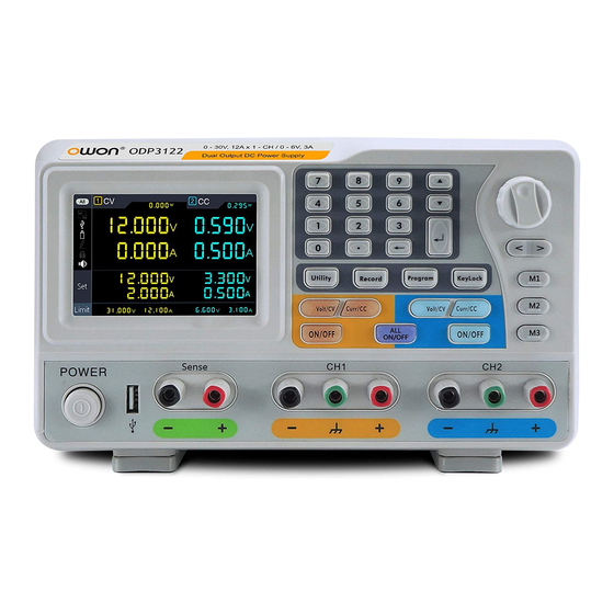
ODP Series Dual Output
Linear Programmable DC Power Supply
User Manual
■ ODP3122
■ ODP6062
Table of
Contents
Previous
Page
Next
Page
1
2
3
4
5
Advertisement
Table of Contents
Need help?
Do you have a question about the ODP Series and is the answer not in the manual?
Ask a question
Questions and answers
Related Manuals for Owon ODP Series
Power Supply Owon ODP Series User Manual
Odp series digital power supply (32 pages)
Power Supply Owon ODP3033 User Manual
Triple output linear programmable dc power supply (31 pages)
Power Supply Owon ODP3032 User Manual
Odp series linear programmable dc power supply (33 pages)
Power Supply Owon ODP3031 User Manual
Linear programmable dc power supply (29 pages)
Power Supply Owon ODP3122 User Manual
Dual output linear programmable dc power supply (29 pages)
Power Supply Owon ODP6062 User Manual
Dual output linear programmable dc power supply (29 pages)
Power Supply Owon OWP H Series User Manual
(34 pages)
Power Supply Owon OWP3006H User Manual
(34 pages)
Power Supply Owon ODP3063 User Manual
Triple output linear programmable dc power supply (31 pages)
Power Supply Owon ODP6033 User Manual
Triple output linear programmable dc power supply (31 pages)
Power Supply Owon OWH67 Series User Manual
Program power supply (43 pages)
Power Supply Owon OEL85 Series User Manual
Programmable dc electronic load (48 pages)
Power Supply Owon OEL8511 User Manual
Programmable dc electronic load (48 pages)
Power Supply Owon OEL8512 User Manual
Programmable dc electronic load (48 pages)
Power Supply Owon ODP8000 Series User Manual
Programmable dc power supply (42 pages)
Power Supply Owon SPE Series User Manual
Single channel output dc power supply (19 pages)
This manual is also suitable for:
Odp3122
Odp6062
Table of Contents
Print
Rename the bookmark
Delete bookmark?
Delete from my manuals?
Login
Sign In
OR
Sign in with Facebook
Sign in with Google
Upload manual
Upload from disk
Upload from URL


Need help?
Do you have a question about the ODP Series and is the answer not in the manual?
Questions and answers