Table of Contents
Advertisement
Quick Links
INSTRUCTION MANUAL
N° 2
07/2009
PLEASE READ CAREFULLY AND UNDERSTAND BEFORE USING THE
EQUIPMENT
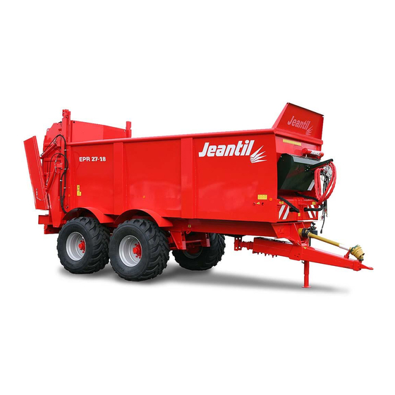
MANURE SPREADER EPR
1000 revs/min
EPR 23-16 Bogie
EPR 23-18 Axle
EPR 27-18 Axle
EPR 27-20 Axle
JEANTIL
Rue de la Tertrais
ZI La Hautière BP1
35590 L'HERMITAGE France
Tel: 00 33 (0)2.99.64.04.04
Fax: 00 33 (0)2.99.64.19.56
Spare parts shop tel: 00 33 (0)2.99.64.04.02
Spare parts shop fax: 00 33 (0)2.99.64.09.36
1
Advertisement
Table of Contents

Related Manuals for JEANTIL EPR Series

Summary of Contents for JEANTIL EPR Series
- Page 1 MANURE SPREADER EPR 1000 revs/min EPR 23-16 Bogie EPR 23-18 Axle EPR 27-18 Axle EPR 27-20 Axle JEANTIL Rue de la Tertrais ZI La Hautière BP1 35590 L’HERMITAGE France Tel: 00 33 (0)2.99.64.04.04 Fax: 00 33 (0)2.99.64.19.56 Spare parts shop tel: 00 33 (0)2.99.64.04.02...
-
Page 2: Contact Details (Customer Service)
E-mail: jeantil@jeantil.com – Web site: www.jeantil.com 1. Aim of the Instruction Manual 1). General The manual concerns all users of the equipment and any person responsible for assembling, installing, operating, adjusting, servicing, repairing or transporting the equipment and its accessories. -
Page 3: Statement Of Compliance With The European 'Equipment' Directive
And to any relevant transposition regulations The manufacturer: JEANTIL Rue de la Tertrais ZI de La Hautière 35590 L’HERMITAGE – France DECLARES THAT THE EQUIPMENT manufactured by JEANTIL as designated below: Spreader, bogie EPR 23-16 Spreader, 2 axles EPR 23-18... -
Page 4: Table Of Contents
2. Contents Aim of the instruction manual General Erreur ! Signet non défini. Warning symbols Erreur ! Signet non défini. Keeping the manual Erreur ! Signet non défini. Contact details (customer service) Statement of compliance with the European ‘equipment’ directive Contents Equipment identification Standard operating conditions... - Page 5 Adjustments and maintenance Greasing Oil change Various advice Chains Wheels Hydraulic hoses Speed of moving floor’s hydraulic motor Torque limiter 8.a. On secondary transmission. 8.b. Adjustments (re-calibration) Hydraulic safety valves 10). Door safety valve 11). Short period uses 10. Start-up and operation Important information Loading Spreading...
-
Page 6: Equipment Identification
3. Equipment identification 35590 L'HERMITAGE - FRANCE P.T.A.C. Type Anneau N° de Masses Essieu 1 série maximales Essieu 2 admissibles Année de construction Essieu 3 Réceptionné Ref: 892 770 Manufacturer’s plate to EC standards. Never remove the manufacturer’s plate and the EC marking fixed to the equipment. -
Page 7: Standard Operating Conditions
4. Standard operating conditions 1). Applications of the equipment. This equipment is intended exclusively for general agricultural purposes i.e.: transporting and spreading manure, transporting silage. Any other use falls outside normal usage and is therefore forbidden. For any other use, please contact the manufacturer. 2). -
Page 8: Technical Characteristics
Only use spare parts and accessories that comply with the manufacturer’s recommendations. Do not carry out any modifications yourself and do not allow others to modify your equipment and its accessories (mechanical, electrical, hydraulic or pneumatic characteristics) without requesting prior written approval from the manufacturer. Failure to comply with these requirements may make the machinery dangerous. -
Page 9: Stowing Diagram
● ● ● ● Guillotine door ● ● ● ● Spring drawbar ● ● ● ● Hydraulic stand ● ● ● ● Load transfer ● ● ● ● Spreader meter ● ● ● ● side shutter Hydraulic power unit ■ ■... -
Page 10: General Safety Rules
6. General safety rules. 1). General. Never forget that knowledge, awareness and caution are the best way to ensure your safety. Regulations and rules relating to accident prevention, health and safety at work, and the operation of vehicles on the public highway must be observed at all times. Chapter 4 (Standard operating conditions) of this Instruction Manual, contains basic directives that must be followed for the sake of your safety. -
Page 11: Warning / Pictograms
2). Warning / Pictograms. 1. Warnings and pictograms placed on the equipment provide information about safety measures to be taken, that will contribute to avoid accidents. 2. Make sure that these warnings and pictograms remain clean and legible. If they are damaged, ask for new stickers from the manufacturer (or agent). - Page 12 Stickers for use of equipment. Ref: 892 651 Placed on the left side of the drive shaft casing Ref: 892 703 EP with distributor and rear cover Ref: 892 653 Placed at the back of the mudguards Ref: 892 687 Placed on the right and left sides, at the back of the...
- Page 13 Ref: 892 453 Placed above right and left tail lights Ref: 892 227 Placed on the front right and left sides of body Ref: 892 299 Placed on rear left, next to the valve of rear door Ref: 892 230 Placed at the front of the spreader...
-
Page 14: Coupling
3). Coupling. 1- See chapter 5, Technical characteristics, pages 8 and 9. 2- Hitching the machine to the tractor must only be carried out using the tractor’s rear coupling points provided for this purpose. 3- Check the compatibility of the machine with the tractor (minimum engine power, type of coupling, tractor PTO characteristics, etc.). -
Page 15: Pto / Drive Shaft
5). PTO (power take-off) / Drive shaft. 1- Read and learn the manufacturer’s instructions for the drive shaft. 2- Check that the PTO guards are in place and in a good condition. Replace them immediately if damaged. 3- Adjust the length between the tractor and the machine, retaining maximum engagement. -
Page 16: Welding Operations
13- Allow any component likely to be at a high temperature to cool down. 6.b. Welding operations. 1- When carrying out any welding operation on the equipment, disconnect the electric connector and the tractor battery. 2- Disconnect and protect any hoses (particularly rubber) and any electric cables to ensure that they are not damaged by incandescent particles that could cause oil loss or a short circuit. -
Page 17: Environmental Protection
4- Damaged or defective protective devices or casings must be replaced immediately. 5- Any original protective device fixed to the equipment must not be removed or modified. 6- Hydraulic hoses that originate from another hydraulic system must not be re-used. 7- When a rigid or flexible line is damaged, it must be replaced immediately. -
Page 18: Secondary Drive Shaft
Read the manufacturer’s instructions concerning the drive shaft, attached to the transmission. Check the safety conditions of the guard. If it shows any sign of damage, it must be replaced before the equipment is used. The drive shaft is placed between the tractor and the spreader. Fit the spreader’s primary drive shaft to the tractor’s rear PTO outlet, and adjust its length, retaining maximum engagement. -
Page 19: Electricity
11- Tractor with flow which exceeds 45 l/min: Provide a flow divider to be installed on the spreader, before the “PRESSURE” orifice on the distributor unit, or contact your dealer to check whether it is possible to adjust the tractor’s flow rate. 12- Closed circuit tractor: (Example: John DEERE) a- To operate the equipment without the tractor having problems, activate the tractor distributor and immediately use the equipment’s hydraulic functions. -
Page 20: Oil Change
- 2 greasers on rear shaft bearing of moving floor (Reference 4). - Greasers located on both sides of the spreading system (Reference 5). 3- Regularly oil hinges and pins which are not fitted with greasers. GREASING DIAGRAM: 2). Oil change. The oil change of all gearboxes should be carried out at least once a year, depending on the frequency of use: SAE 90... -
Page 21: Various Advice
3). Various advice. - Occasionally check the tightness of the 3 assembly bolts of the gearbox output shaft coupling sleeves. These bolts ensure the safety of the spreader’s mechanical parts and the tractor PTO, by breaking off if the rotors or moving floor are jammed. - After 10 hours of use check the wheel locking system. -
Page 22: Hydraulic Hoses
Inflation Tyre width Load per Profile Dimensions Diameter pressure in bars (unloaded) wheel in kg (unloaded) (40km/h) (mini – mini - maxi maxi) 600/55R 26,5 1,34 m 0,63 m 2495 - 7100 0,8 - 4 (Standard) 680/55R 26.5 (Option for 1,4 m 0,67m 2995 - 6900... -
Page 23: Torque Limiter
2- The flow regulator vernier scale graduated 0-1-2-3-4-5, and located behind a transparent screen on the front housing, is used to control the adjustment. 8). Torque limiter. 8.a. On secondary transmission. 1- It protects the spreading device against overload, foreign matters and an excessive speed of the moving floor. - Page 24 Adjustment Longuest Shortest Number Limiter External value adjustment adjustment Spring type type diameter 1mm = 1 turn dimension dimension springs Corresponds to maxL (mm) minL (mm) about 35,0 K 64/22 170 mm 60x20,5 x 2,0 53,0 47,5 daNm NOTE To avoid the limiter getting stuck, it is important to make sure, during the adjustment or readjustment, that the shortest adjustment dimension is not lower than the indicated dimension.
-
Page 25: Hydraulic Safety Valves
2- If there are foreign matters, remove them before starting the spreader again. 3- Be extremely careful (see safety section). 9). Hydraulic safety valves. 1- All distributors are equipped with a hydraulic safety valve, set at 180 bars, located at the pressure inlet of the distributor unit. 2- To check the valve calibration, connect a pressure gauge in parallel on the pressure line: a- With hydraulic door:... -
Page 26: Loading
1- Our spreaders will give reliable and satisfactory service if used within their normal limits. 2- Never exceed the maximum load indicated on the manufacturer plate. 3- Before loading the spreader when it is used for the first time and every time it is used after a period of inactivity, operate the moving floor so that it goes round once. -
Page 27: Quantity To Spread Per Hectare
- When the spreading is finished: - Put the distributor in neutral, then disengage the tractor PTO. - Do not take a bend or turn when the tractor PTO is on. 4). Quantity to spread per hectare. When you know the quantity of manure K (in tonnes) that you want to spread per hectare, proceed as follows: 1 –... -
Page 28: Independent Hydraulic Power Unit
2). Independent hydraulic power unit. SAFETY As the pump is driven by the rotating PTO, do not forget to put the control distributors for hydraulic parts in neutral such as the moving floor, heavy slurry door…etc. FUNCTION Avoids using the tractor’s hydraulic circuit. - Activate the tractor’s PTO. -
Page 29: Grain And Silage Extension
1- Carefully check that the door is not in contact with an electric line as there is a potential risk of electrocution. 2- The guillotine door is equipped with a hydraulic safety system, which stops the moving floor if the door is not open enough. FUNCTION It enables to halt and control the quantity of product to spread such as liquid and viscous products. -
Page 30: Hydraulic Stand
MAINTENANCE - The hydraulic circuit of the load transfer is protected against overload with a pressure relief valve set at 120 bars. - Regularly grease the hinges of the cylinders and the trunnions of the sleeves which slide over the bases. 7). - Page 31 4. Raise the front of the spreader as high as possible to make the water drain away towards the back. 5. Raise the slurry door and lock it with the safety valve. 6. Unlock the access ladder to enter the body for an internal cleaning. 7.
-
Page 32: List Of Technical Documents
13. List of technical documents. - 911001-1-A: Horizontal beater device - 911002-1-A: Left side of device - 911003-1-A: Lower beater - 911004-1-A: Upper beater - 911005-1-A: Chain tensioner - 911006-1-A: Tensioning sprocket - 911007-1-A: Spreading disc - 911008-1-A: Spreading table - 911009-1-A: Guillotine door - 911010-1-A: EPR casings - 911011-1-A: Moving floor... - Page 33 - 911016-1-A: Hydraulic diagram of tandem braking...
-
Page 34: Possible Incidents And Solutions
14. Possible incidents and solutions. INCIDENTS CAUSES AND SOLUTIONS 1 – The safety bolts of the rotor’s drive shaft - Reduce the speed of the moving floor. keep breaking off - Check hydraulic connection of spreader and 2 - Abnormal functioning of all hydraulic tractor single-acting distributor.
Need help?
Do you have a question about the EPR Series and is the answer not in the manual?
Questions and answers