Table of Contents
Advertisement
Quick Links
【
Operation Manual 】
Compact digital meter
Series name
SP2441
! Caution
For professional use only or designed for use by a licensed electrician only.
! Caution
Check if the label (model name) of the unit and your desired product
specification correspond before use.
MODEL : SP2441 Series
(Pulse input type)
Output
Input
P1
AI
AV3
AV4
AV5
F
F2
Function
Sensor power : DC12V 50mA MAX
Power source : DC power supply(DC24V)
Preset output : NPN open collector(×2)
Input signal : NPN open collector(×1)
Color : Black
Preset output one points
(1c contact relay output)
Analog current output (DC4-20mA)
Analog voltage output (DC1-5V)
Analog voltage output (DC0-5V)
Analog voltage output (DC0-10V)
Voltage pulse input
Current pulse input
【 The 3rd edition 21 Aug. 2020 】
@SP2441CE(3)-E
Advertisement
Table of Contents

Related Manuals for UINICS SP2441 Series

Summary of Contents for UINICS SP2441 Series
- Page 1 【 Operation Manual 】 Compact digital meter MODEL : SP2441 Series (Pulse input type) Series name Output Input Function Sensor power : DC12V 50mA MAX Power source : DC power supply(DC24V) SP2441 Preset output : NPN open collector(×2) Input signal : NPN open collector(×1) Color : Black Preset output one points (1c contact relay output)
- Page 2 Precautions recautions recautions Please read this Operation Manual including the following precautions carefully to ensure Please read this Operation Manual including the following precautions carefully to ensure Please read this Operation Manual including the following precautions carefully to ensure Please read this Operation Manual including the following precautions carefully to ensure Please read this Operation Manual including the following precautions carefully to ensure Please read this Operation Manual including the following precautions carefully to ensure Please read this Operation Manual including the following precautions carefully to ensure...
-
Page 3: Table Of Contents
Contents 1. About confirmation of an attachment. and a guaranteed period ・・・・・・・・ 1 2. Specifications ・・・・・・・・・・・・・・・・・・・・・・・・・・・・・・・ 2 - 4 3. Mounting meter ・・・・・・・・・・・・・・・・・・・・・・・・・・・・・・・・ 5 4. Connecting terminal boards ・・・・・・・・・・・・・・・・・・・・・・・・ 6 - 7 5. Construction of input/output circuit ・・・・・・・・・・・・・・・・・・・・8 - 9 6. - Page 4 11. The mode protect function ・・・・・・・・・・・・・・・・・・・・・・・・・ 33 12. Calling up and modifying the offset value setting ・・・・・・・・・・・・・・・ 34 13. Calling up and modifying the preset value setting ・・・・・・・・・・・・・・・ 35 14. Adjusting the analog output (option)・・・・・・・・・・・・・・・・・・・ 36 - 37 15. External dimensions ・・・・・・・・・・・・・・・・・・・・・・・・・・・・・ 37 16.
-
Page 5: About Confirmation Of An Attachment And A Guaranteed Period
1. About confirmation of an attachment and a guaranteed period About confirmation of attachments. When you received as a product, please confirm whether it includes the following. (1)SP2441 (The chosen specification) ・・・・・・・・・・・・・・・・・・1 (2)Installation adapter(Attachment) ・・・・・・・・・・・・・・・・・・・・1 (3)SP2441 Operation manual (Digest version) ・・・・・・・・・・・・・・1 (4)Rubber packing : Color (Black)(Attachment)・・・・・・・・・・・・・・・1... -
Page 6: Specifications
2. Specifications 【 Standard specifications 】 Items Specifications Type Ratemeter/Totalizer Measurement Cycle calculation method Method Display Red LED : 5 digits, Character height : 7mm(range : 0 - 99999) Display Display switching Rate meter/Totalizer ±0.05%rdg.±1digit Display accuracy ( at Sampling time for 0.5 second or more ) -9... - Page 7 Output method NPN open collector output.(×2) Maximum rating DC30V 50mA(max.) Comparative method The upper limit, lower (immediately) and lower (delay). Preset Compared with the indication value by preset value. Output mode output Comparison, hold and 1 shot. The presetting output function is disabled for the specified time Judgment interval following power ON or reset.
- Page 8 【 Option specifications 】 ≪Relay output : P1 option≫ Output method Relay c contact output(×1) Preset output AC220V 0.12A (Resistance load) Maximum rating DC 30V 1A (Resistance load) ≪Analog output : AI/ AV3 - 5 option≫ [AI] DC4 - 20mA Load impedance 500Ω or less. *Connect to the power supply-side and the floating input Output signal [AV3] DC1 - 5V Load impedance 2kΩ...
-
Page 9: Mounting Meter
3. Mounting meter How to mount meter 1. Cut the panel to insert the meter from the front. 2. Slide installation adapter from the rear to fix the body. At this time, if the body is not secured tightly, fasten screws a little more. ・Put the meter on a panel with a thickness of 1.0 –... -
Page 10: Connecting Terminal Boards
4. Connecting terminal boards Terminal boards Fig.4-1 【 Standard type 】 Fig.4-2 【 P1 option type 】 Terminal pitch : 3.5mm (Phoenix : SMKDS1/12-3.5) 2 Wire : AWG30 – 16 (SQ Conversion : 0.05 – 1.3mm Length of stripped wire : 5.0mm - 6 -... - Page 11 < Connection diagrams> Fig.4-3 Fig.4-4 Sensor another power supply use. Sensor power supply use. DC two-line pulse output sensor Fig.4-5 ! < Caution > Always turn the power OFF before commencing any wiring work. ! < Caution > Please confirm the specification. !...
-
Page 12: Construction Of Input/Output Circuit ・・・・・・・・・・・・・・・・・・・・8
5. Construction of input/output circuit 1. Senser input : NPN open collector pulse input Fig.5-1 2. Senser input : Voltage pulse input Fig.5-2 3. EXT input : NPN open collector input Fig.5-3 - 8 -... - Page 13 4. Analog output : Voltage output (AV3 - 5) Current output (AI) Fig.5-4 Fig.5-5 5. Preset output : Synchronization pulse output (NPN open collector output) 6. P1 Option relay output Fig.5-6 Fig.5-7 - 9 -...
-
Page 14: Setting The Dip Switch
6. Setting the dip switch The input response frequency, NPN open collector pulse input, and voltage pulse input, is selected by setting the dip switch. DSW1-1 DSW1-2 NPN open collecter pulse input OFF⇔ON Voltage pulse input Input response frequency 0.01Hz - 50Hz (LOW) Input response frequency 0.01Hz~10kHz (HI) ※As default setting,... -
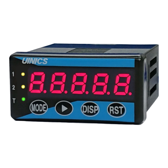
Page 15: Names And Functions Of Components On Front
7. Names and functions of components on front Fig.7-1 1.Display unit(Red) 6.Preset output "OUT1" LED(Orange) 7.Preset output "OUT2" LED(Orange) 8.Totalizer LED(Green) 1. Display unit(Red) Measurement state : A measured value is indicated. Setting state: A・・・・・ Mode No. is indicated. B to E・・・The present set value is indicated. : When preset value setting indicates the preset value. - Page 16 3. Shift Key Measurement state : Shift Key is used to call the mode setting. (It's on for more than 2 sec with Mode Key.) : Shift Key is used to call the mode protect function, or used to change it. (It's on for more than 2 sec.
-
Page 17: The Setting Menu
8. The setting menu ≪The test mode function≫ Fig.8-1 Power supply OFF Turn power supply on with being pressed. Test mode - 13 -... - Page 18 ≪The setting menu≫ Fig.8-2 Power supply OFF Turn power supply on. <Adjusting the analog output> Turn power supply on with being pressed. Turn power supply on with <Operation reset> being pressed. Initialization Measurement state ※After adjusting the setting,use to register it. ※When is pressed for more than 2 seconds, a display returns to measurement indication.
-
Page 19: Initial Setting Values And Initialization
9. Initial setting values and initialization If the specifications desired by the user are requested prior to shipment, the meter will be set these settings. Otherwise, the regular factory settings are shown below. Value setting of each mode Table.9-1 Mode No. Initial setting Notes Mode contents... -
Page 20: Content And Setting The Each Mode
10. Mode setting ≪1. Operating method (the mode setting)≫ When doing mode setting, please operate as follows. Operation key Indication Procedure A B C D E While pushing down Mode Key, press 1.1 0 0 0 Shift Key for 2 sec, or more. +... -
Page 21: Content Of The Each Mode And Set Value≫ ・・・・・・・・・・・・17
≪2. Contents of the each mode and set value≫ Mode No. Ratemeter : Setting of scaling data A B C D E 1. 1 0 0 0 Scaling data 0001-9999 (Do not specify 0000.) Input scaling is performed for the rate meter reading. By specifying the scaling data and the exponential value (a minus power of 10), the scaling ratio per pulse can be set. -
Page 22: Calculation Example Of Scaling Data (Setting Example)
Calculation example of scaling data (setting example) Example Arithmetic expression In case of " Revolution " Scaling data=1revolution/pulse Arithmetic In case of " Speed " expression Scaling data=Amount of transfer/pulse In case of " Flow " Scaling data=Flow rate value/pulse Factor →1 revolution/1 pulse = 1 〔Ex.1〕... -
Page 23: The Unit Time And The Decimal Point
Rate meter : Setting of Exp. value, least significant digit , Mode No. the unit time and the decimal point A B C D E 2 2. 3 0 1 1 Decimal point 0 : 0.0000 1 : 0000.0 2 : 000.00 3 : 00.000 4 : 0.0000 Unit time... -
Page 24: Mode 3 "Ratemeter : Setting Of The Sampling Time
Mode No. Ratemeter : Setting of the sampling time A B C D E 3. 0 2.0 Sampling time 00.1-99.9 seconds ("00.0" is "100 sec"). 【 Sampling time 】 Input signals are read by this time, and its average value is calculated and indicated. -
Page 25: Mode 5 "Ratemeter : Setting The Auto-Zero Time
【 Display moving average 】 If the moving average count is set to 3 at "Mode No.4", captures 3 times of instantaneous measurement data capture Calculates, captures the next instantaneous measurement data, discharges the oldest instantaneous measurement data, and displays the calculation. ■Example (Moving average count : 3) Rate meter A display... -
Page 26: Mode 6 "Setting Of Ext Input And Measurement Indication
Mode No. Setting of EXT input and measurement indication A B C D E 6. 0 0 6 Indicator 0 : Rate meter/totalizer is switched. 1 : Rate meter is fixed. 2 : Totalizer is fixed. EXT input 0 : Reset 1 : Hold 2 : Inhibit 3 : Indication change... -
Page 27: Mode 7 "Totalizer : Setting Of Scaling Data
Mode No. Totalizer : Setting of scaling data A B C D E 7 7. 1 0 0 0 Scaling data 0001-9999 (Do not specify 0000.) Input scaling is performed for the totalizer reading. By specifying the scaling data and the exponential value (a minus power of 10), the scaling ratio per pulse can be set. - Page 28 【 Reset time 】 Reset time for the front Reset Key is specified. 0 : 2 sec. After the Reset Key is pressed for 2 seconds or longer, the reading is reset. 1 : Immediate The reading is reset immediately when the Reset Key is pressed. !...
-
Page 29: Mode 9 "Setting Of Out1 Preset Output
Mode No. Setting of OUT1 preset output A B C D E 9 9. 0 0 0 0 Output mode(2 - 9 : One shot output) 0 : Comparison 5 : 100ms 1 : Hold 6 : 250ms 2 : 30ms 7 : 500ms 3 : 50ms 1sec. - Page 30 【 Output selection 】 A display to compare with a preset value is chosen. 0 : Rate meter Rate meter is compared with a preset value. 1 : Totalizer Totalizer is compared with a preset value. 2 : Synchronization pulse output It outputs synchronizing with totalizer.
- Page 31 【 Chart at the timing of the preset output 】 【 Chart at the timing of the offset return output 】 - 27 -...
-
Page 32: Mode A "Setting Of Out2 Preset Output
Mode No. Setting of OUT2 preset output ※ Not displayed when P1 option is selected A B C D E A. 0 0 0 0 Output mode (2-9 : One shot output) 0 : Comparison 5 : 100ms 1 : Hold 6 : 250ms ◆... -
Page 33: Mode B "Totalizer : Setting Of The Synchronization Pulse Output
Mode No. Totalizer : Setting of the synchronization pulse output ※ Not displayed when P1 option is selected ! < Caution > * It will function, if the totalizer synchronous pulse output is set up by output selection of the mode No.9. The synchronization pulse is outputted from OUT1 (terminals no. -
Page 34: The Output Digit
Mode No. Analog output(option) : Setting of measurement choice and the output digit * Displayed when analog output option is selected (AI/AV3-5 type). A B C D E C. 0 0 C Digit selection 0 : Right 4 digits : comparison (Display unit B,C,D,E) 1 : Left 4 digits:comparison (Display unit A,B,C,D) - Page 35 【 Digit selection 】 It chooses "the right 4 digits" or"the left 4 digits", and setting. A B C D E Right 4 digits Left 4 digits ! < Caution > ※An analog output is outputting calculation to the indication value shown to 7 segment LED.
-
Page 36: Mode D "Analog Output(Option) : Setting Of Maximum Output Indication
Mode No. Analog output(option) : Setting of maximum output indication ※ Displayed when analog output option is selected (AI/AV3-5 type). A B C D E d.1 0 0 0 d Indication value 0001-9999 (Do not specify 0000.) Set an indication value of the time when the analog output is maximum. - Page 37 11. The mode protect function When the mode protect function is made effective, Display Key operation is invalid by mode setting. Therefore the set value can't be changed. In an early stage, the mode protect function is invalid. When doing the mode protect function setting, please operate as follows. ≪Operation of the mode protect≫...
- Page 38 12. Calling up and modifying the offset value setting The preset totalizer reading value to be displayed directly following a reset is specified. For example, if the offset value is set at "01000", the reading becomes "1000" when reset, and the count resumes from "1000". In order to start the count from "0", the offset value should be set as "00000".
- Page 39 13. Calling up and modifying the preset value setting Set the preset values. "OUT1, OUT2". The setting ranges are 0-99999. The procedure for setting the preset value is described below. ≪Operation of the preset value setting≫ Operation key Indication Procedure A...
- Page 40 14. Adjusting the analog output (option) ! < Caution > ※It's being adjusted according to the analog output option, but when being adjusted by yourself, please setting it with the following procedure. When a power supply is supplied while is pressing Display Key,an analog output adjustment mode setting.
- Page 41 In case of "AV3(1-5V)" In case of "AV4(0-5V)" Items Voltage Items Voltage Adjustment (MIN) 1.000V Adjustment (MIN) 0.000V Adjustment (MAX) 5.000V Adjustment (MAX) 5.000V In case of "AV5(0-10V)" In case of "AI(4-20mA)" Items Voltage Items Current Adjustment (MIN) 0.000V Adjustment (MIN) 4.000mA Adjustment (MAX) 10.000V Adjustment (MAX) 20.000mA...
- Page 42 16. About a noise countermeasure When influence of noise occurred, please be careful about the following. When doing a blackout and a malfunction by influence of noise, please be initialized. (Refer to page 15) Please take notes of the value setting of each modes. If it becomes normal, please take the following measure.
- Page 43 17. Troubleshooting When abnormality occurred, please check it as follows. Problem Checking point Solution Display does not →Has it connected with →Connect correctly according to the rear terminal "Connecting terminal boards" appear at all. correctly? (Refer to page 6). Is the screw tightened ↓...
- Page 44 123-1, Kami, Nishi-ku, Sakai-shi, Osaka, 593-8311 Japan. Tel. 81-72-274-6001 Fax. 81-72-274-6005 ・Tokyo Office Tel. 81-3-5256-8311 Fax. 81-3-5256-8312 U R L https://www.uinics.co.jp Scan the QR code to access the website. Please understand that the specifications of our products may be changed for improvement without notice.
Need help?
Do you have a question about the SP2441 Series and is the answer not in the manual?
Questions and answers