Table of Contents
Advertisement
Quick Links
Advertisement
Table of Contents

Related Manuals for GLW PC 65


Summary of Contents for GLW PC 65
- Page 1 OPERATING INSTRUCTIONS...
-
Page 3: Table Of Contents
Protective cover ................... 13 Control and display elements ..............14 4.5.1 Starting up the PC 65 .................. 14 4.5.2 Operating the foot pedal (crimping) ............. 15 4.5.3 Operating pressure ..................15 PC 65 Crimper Operating Instructions – Vers. 1.0 Page 3 of 39... - Page 4 Table of contents 4.5.4 Unlocking the display .................. 16 4.5.5 Starting up the PC 65 (operating mode 2) ........... 16 4.5.6 Operating the foot pedal (operating mode 2) ..........17 4.5.7 Switching from standard to setting on-screen display ......... 18 4.5.8...
- Page 5 10.2 Spare parts ....................36 10.3 Accessories....................36 10.3.1 Crimp dies ....................36 10.3.2 Protective cover ................... 37 10.3.3 Locator unit....................37 11 Declaration of Conformity ..............38 12 Copyright ................... 39 PC 65 Crimper Operating Instructions – Vers. 1.0 Page 5 of 39...
-
Page 6: General Information
Prior to using this equipment, the operating personnel must make themselves familiar with the operating instructions and the product. Adhering to all safety instructions is the fundamental requirement for the application of the PC 65 crimper. The operating instructions are an integral part of the product, and must therefore be passed on in case the equipment is sold, disposed of or moved to a different site. -
Page 7: Safety Instructions
Hazards posed by the risk of getting crushed Operating instructions Disposal of old electrical and electronic devices 1., 2… Instructions Outcome of the instructions Averting the hazard PC 65 Crimper Operating Instructions – Vers. 1.0 Page 7 of 39... -
Page 8: General Safety Instructions
Furthermore, intended use includes adherence to supplier documentation. Any other use shall be deemed as improper use. GLW shall not assume liability for any damage resulting from improper use. Use of the equipment for purposes other than the intended use If the equipment is operated without meeting the specifications, it shall be deemed improper use. -
Page 9: Proper Conduct During Emergencies
Never carry out any work without the protective cover in place. 2.12 Qualification of the personnel Only trained and instructed personnel is allowed to operate the equipment. PC 65 Crimper Operating Instructions – Vers. 1.0 Page 9 of 39... -
Page 10: Personal Protective Equipment
The environmental and health regulations must be followed and require appropriate conduct. For further details, refer to section 9.3 Dismantling and disposal in the supplier documentation and the relevant safety data sheets. PC 65 Crimper Operating Instructions – Vers. 1.0 Page 10 of 39... -
Page 11: Transport And Storage
We recommend to use the original operating instructions or the relevant translation of the suppliers (purchased parts). For transport overseas, packaging appropriate for oversea transport must be used. PC 65 Crimper Operating Instructions – Vers. 1.0 Page 11 of 39... -
Page 12: Product Description
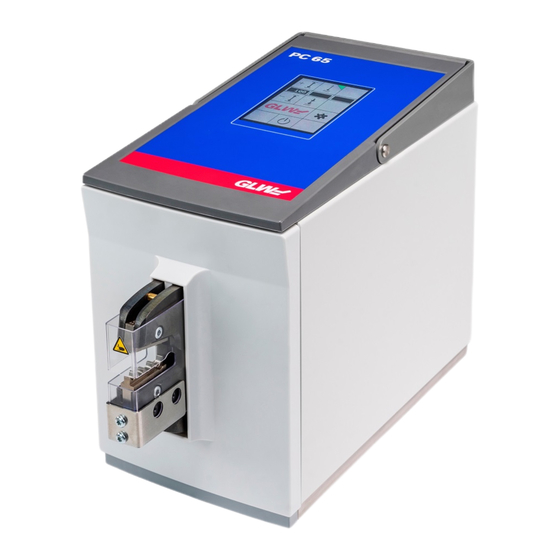
Protective cover 12 VAC power supply Carrier handle Signal output for PC 65 accessories Rocker switch “ON / OFF” Power supply unit 12 VAC, 500 mA, 6.0 W max. PC 65 Crimper Operating Instructions – Vers. 1.0 Page 12 of 39... -
Page 13: Accessories
A protective cover with an accurately fitted insertion slot is provided for each crimp die. For this purpose, also refer to www.glw.de/crimper. The PC 65 will only work if the protective cover is inserted completely. The protective cover protects against injuries to fingers and hands in the hazard zone of the crimp die and against damage from the outside. -
Page 14: Control And Display Elements
4 Product description Control and display elements All settings regarding the operation of the PC 65 are carried out on the display. Buttons with a 3D effect are controllable. Flat buttons are deactivated. For the operating mode buttons, the active operating mode shows a green triangle in the upper right box. -
Page 15: Operating The Foot Pedal (Crimping)
The process must be repeated Foot pedal It shows the last successful crimp processes (1234 here) 5.2.4 Adjusting the operating pressure 4.5.11 Adjusting to min. pressure 4.5.12 Adjusting to max. pressure PC 65 Crimper Operating Instructions – Vers. 1.0 Page 15 of 39... -
Page 16: Unlocking The Display
In the following sections, the control and display elements that are added for operating mode 2 will be described. 4.5.5 Starting up the PC 65 (operating mode 2) PC 65 Crimper Operating Instructions – Vers. 1.0 Page 16 of 39... -
Page 17: Operating The Foot Pedal (Operating Mode 2)
It shows the operating pressure of the last crimp process (0.58 MPa here) Status window Last OK crimp The equipment is ready for the next work process 6.2.8 Cancelling the contact fixing process PC 65 Crimper Operating Instructions – Vers. 1.0 Page 17 of 39... -
Page 18: Switching From Standard To Setting On-Screen Display
NOTICE For a detailed description of the operating and display elements in the setting on-screen display, also refer to section 6 Operating modes of the PC 65 crimper 4.5.7 Switching from standard to setting on-screen display Fig. 11: Switch on-screen display... -
Page 19: Saving The Opening Angle Of The Crimp Die
Legend Item Description Meaning Load It saves the current settings for the crimp process Information window It prompts you to enter data 6.2.3 Loading the saved opening anglei PC 65 Crimper Operating Instructions – Vers. 1.0 Page 19 of 39... -
Page 20: Locking The Display
Input of the minimum operating pressure Information window It prompts you to enter data 5.2.4 Setting the operating pressure 7.1 Operating pressure too low 7.2 Operating pressure too high PC 65 Crimper Operating Instructions – Vers. 1.0 Page 20 of 39... -
Page 21: Setting The Max. Pressure
Information window It prompts you to enter data (new lock code) Information window It prompts you to enter data (repeat new lock code) 6.2.6 Changing the lock code PC 65 Crimper Operating Instructions – Vers. 1.0 Page 21 of 39... -
Page 22: Requesting A Service Code
Meaning Customer Support Information window It prompts you to enter data 4.5.15 Selecting the language Fig. 19: Select language on-screen display Legend Item Description Meaning Selecting the language PC 65 Crimper Operating Instructions – Vers. 1.0 Page 22 of 39... -
Page 23: Installation And Commissioning/Start Up
Compressed air connection Protective cover Pneumatic coupling Power supply unit 12 VAC, 500 mA, 6.0 W max. Foot pedal Operating instructions PC 65 crimper equipment 5.1.1 Pneumatic installation PC 65 Crimper Operating Instructions – Vers. 1.0 Page 23 of 39... -
Page 24: Electrical Installation
5. Turn the toggle switch from “OFF“ position to “ON“ position. 6. Remove the protective cover (5) and reattach it. 7. Crimp process settings, 6 operating modes of the PC 65 crimper 5.2.1 Starting up the PC 65 crimper The protective cover must be removed and reattached once after start up. -
Page 25: Shutting Down The Pc 65 Crimper
5.2.2 Shutting down the PC 65 crimper The PC 65 crimper is shut off on the back of the equipment by pressing the toggle switch (0), or on the display. If no crimp cycle is started within 30 minutes, the PC 65 shuts off automatically. - Page 26 5 Installation and commissioning/start up Fig. 22: Switch off PC 65 Crimper Operating Instructions – Vers. 1.0 Page 26 of 39...
-
Page 27: Operating The Foot Pedal
The error is acknowledged by activating the X-button (3). The foot pedal is ready to operate (4) again. Fig. 24: Error message during operation of the foot pedal PC 65 Crimper Operating Instructions – Vers. 1.0 Page 27 of 39... -
Page 28: Setting The Operating Pressure
5.2.4 Setting the operating pressure For the PC 65 crimper function, a permissible operating pressure between 0.45 and 0.65 MPa is pre-set in the factory. Depending on the type of the crimp contact, the crimp force can be changed via the pressure controller. -
Page 29: Operating Modes Of The Pc 65 Crimper
6 Operating modes of the PC 65 crimper Operating modes of the PC 65 crimper Operating mode 1 6.1.1 Crimping in one step (button 1) The opening stroke of the crimp die is adjusted to the crimp contact size via display buttons 2 and 4. A smaller opening stroke means a shorter crimp cycle. -
Page 30: Saving The Opening Angle Of The Crimp Die
6 Operating modes of the PC 65 crimper 6.2.2 Saving the opening angle of the crimp die Fig. 29: Save the opening angle of the crimp die 6.2.3 Loading saved opening angles Fig. 30: Load saved opening angles 6.2.4 Locking the display The display can be locked with a code. -
Page 31: Changing Lock Codes
Setting the operating pressure The minimum and/or maximum operating pressure of the PC 65 set as default at the factory is 0.45 MPa (4.5 bar) and 0.65 MPa (6.5 bar). The equipment operates within this pressure range. If these values are exceeded or undercut, the display will show an error message and block further operation. -
Page 32: Cancelling The Contact Fixing Process
6 Operating modes of the PC 65 crimper 6.2.8 Cancelling the contact fixing process If the crimp contact has not been fixed in the proper position, the process can be cancelled by activating the X-button. Fig. 36: Cancel contact fixing process 6.2.9... -
Page 33: Error Messages
Dies have not been adjusted properly Disconnect the compressed air supply. Readjust the die, see 5.3. 5.2.4 Setting the operating pressure Decommissioning Disconnect the equipment from the electrical and compressed air network. PC 65 Crimper Operating Instructions – Vers. 1.0 Page 33 of 39... -
Page 34: Technical Specifications
Output 6.0 W max. Temperature +10 to +40 °C Relative humidity 30 to 90 % Slope/grading max. 3° Tab. 1, Technical specifications Rating plate Fig. 40: Rating plate PC 65 Crimper Operating Instructions – Vers. 1.0 Page 34 of 39... -
Page 35: Instructions Regarding Cleaning, Maintenance And Disassembly
Maintenance carried out by the manufacturer Specialised Crimp processes personnel Dismantling and disposal At the end of usage of the PC 65 crimper, it must be disposed of properly and professionally according to statutory regulations applicable on site. NOTICE Carefully separate the electrical and electronic waste. -
Page 36: Service, Spare Parts And Accessories
GLW GmbH Steinbeisstr. 2 Telephone +49 (0) 7563 / 9123-0 D-88353 Kißlegg email service@glw.de 10.2 Spare parts The following table contains spare parts defined for the PC 65 crimper. Figure Spare part designation Order number Crimp die www.glw.de Protective cover www.glw.de Foot pedal www.glw.de... -
Page 37: Protective Cover
Fasten the locator unit (1) with the two screws (2) Depending on the type, the locator unit can be attached either on the left or the right side on the lower crimp lever EC Declaration of Conformity PC 65 Crimper Operating Instructions – Vers. 1.0 Page 37 of 39... -
Page 38: Declaration Of Conformity
Safety of machinery - Safety-related parts of control systems - Part 1: General design principles EN ISO 13857: 2008 Safety of machinery — Safety clearances to prevent hazard zones being reached by upper and lower limbs Kißlegg, 02/08/2019 Management PC 65 Crimper Operating Instructions – Vers. 1.0 Page 38 of 39... -
Page 39: Copyright
12 Copyright Copyright Copyright © 2019 GLW GmbH, Kißlegg. All rights reserved. All product and company names are trademarks or registered trademarks of their respective owners. No part of these operating instructions may be duplicated, published or transmitted in any form with- out the explicit written consent of the GLW GmbH.
Need help?
Do you have a question about the PC 65 and is the answer not in the manual?
Questions and answers