Advertisement
Quick Links
Advertisement

Related Manuals for Delton 770J

Summary of Contents for Delton 770J
- Page 1 DIGITAL AUTO MOTIVE ANALYSER 770J / 770K...
- Page 2 Thank you for purchasing the product. Manufactured to a high standard this product will, if used according to these instructions and properly maintained, give you years of trouble free performance. IMPORTANT: PLEASE READ THESE INSTRUCTIONS CAREFULLY. NOTE SAFE OPERATIONAL REQUIREMENTS, WARNINGS & CAUTIONS. USE THE PRODUCT CORRECTLY AND WITH CARE FOR THE PURPOSE FOR WHICH IT IS INTENDED.
- Page 3 √ Before commencing testing, follow instructions below and select the correct input sockets, function and range on the multimeter. √ When the meter is connected to a circuit, do not touch any unused meter terminals. √ When the magnitude of the value to be measured is unknown beforehand, set the range selector to the highest value available.
- Page 4 disconnect the power when making resistance or diode tests. DO NOT use the multimeter in a potentially explosive atmosphere × or where flammable material is present. ONLY operate the multimeter when the back cover is in place and √ fastened securely. If any abnormal readings are observed, the multimeter must be √...
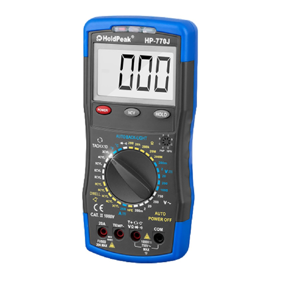
- Page 5 Includes relative functions including Min/Max and Peak Hold. Supplied with Inductive Coupler, test probes and thermocouple in carry case. SPECIFICATION..........Model No: 770J, 770K Diode Check......Yes Tach (RPM)...2-10cyl, 4-Stroke 60-9000 (x1)rpm, 600-12000 (x10)rpm Auto Back-Light.....Yes...
- Page 6 3. MAIN METER FEATURES 4. PUSH BUTTON FUNCTIONS 4.1 Manual Range & Stroke 4/2(DIS), DUTY%, ms, CYL Button(Fig 3) Press to this button to select: STROKE 4, 2 DIS, DUTY%, ms-PULSE, CYL range & V/A/R/CAP/Hz manual Range. Fig.3...
- Page 7 Manual Ranging(Fig 3) The meter turns on in the auto-ranging mode. Press the Range button to go to manual ranging. The display icon " " will appear. Each press of the range button will step to the next range as indicated by the units and decimal point location.
- Page 8 4.4.3 The display will update each time a higher positive peak occurs. 4.4.4 Press the PEAK button again, Peak MIN will display. The display will now update and indicate the lowest negative peak. 4.4.5 To return to normal operation, press and hold the PEAK button until the Peak MAX or PEAK MIN indicator switches off.
- Page 9 5.1.2 Press the “SELECT” button to choose DC or AC voltage measurement. 5.1.3 The meter will automatically select the best voltage range. 5.1.4 Insert Black lead in COM terminal. 5.1.5 Insert Red lead in VΩHz terminal. 5.1.6 Touch the Black probe to ground or to the negative (-) circuit. 5.1.7 Touch the Red probe to the circuit coming from the power source.
- Page 10 DIODE (- to +) Reverse probes (+ to -) 0.4 to 0.9V Over Limit (OL) GOOD Over Limit (OL) 0.4 to 0.9V Over Limit (OL) 1.0 to 3.0V 1.0 to 3.0V Over Limit (OL) 0.4 to 0.9V 0.4 to 0.9V Over Limit (OL) Over Limit (OL) 0.000V...
- Page 11 Note: The measurement time of 10mF and 60mF modes is a little long (MAX Aprox. 7s) . In order to obtain an accurate reading, a capacitor must be discharged before measurement begins. Discharging through the chip quite slow. We recommend the user to discharge the capacitor with some other apparatus. 5.6 DC or AC Current (DCA or ACA) IMPORTANT: All current measured flows through the meter.It is important that you do not:...
- Page 12 5-7 DC or AC 600A Current (by clamp adapter) 5.7.1 Select the “ " function with the rotary switch, it shows symbol for testing DC current, if you want to test AC current, push “SELECT” button switch. 5.7.2 Connect the black banana plug of the AC/DC Current Clamp Adapter to COM terminal and the red banana plug to the mAT+ terminal.
- Page 13 Frequency (Hz) 5.9.1 Select the “Hz” Frequency function with the rotary switch. 5.9.2 Insert the black lead into the COM terminal. 5.9.3 Insert the red lead into the VΩHz terminal. 5.9.4 Connect the Black test probe to ground. 5.9.5 Connect the Red test probe to the “signal out” wire of the sensor to be Tested.
- Page 14 5.12 ms-PULSE (Pulse Width) & ms- PERIOD (Period) 5.12.1 Pulse Width is the length of time an actuator is energized. For example, fuel injectors are activated by an electronic pulse from the Engine Control Module (ECM). This pulse generates a magnetic field that pulls the injector nozzle valve open.
- Page 15 5.12.8 Touch the Red test probe to the fuel injector solenoid driver input on the jumper cable. 5.12.9 Start the engine. A pulse width in milliseconds should be read. Note: Initially, the unit will read “OL”, then readings will descend and stabilize to the actual pulse width.
- Page 16 5.13.9 RPM 4 : For RPM of 4-stroke engines which have 1 ignition on every 4 engine Strokes 5.13.10 RPM 2 : For RPM of DIS ( Distributor less lgnition System) & 2-stroke engines which Have 1 ignition on every 2 engine strokes PLEASE NOTE - THE RPM PICK-UP HAS AN ADJUSTABLE SENSITIVITY SWITCH THAT CAN ALSO BE USED TO...
- Page 17 6000 counts LCD display Display with function indication Automatic, (-) negative Polarity polarity indication. Overrange "OL" marks indication " " is displayed when the Low battery indication battery voltage drops below the operating level Measurement rate 3 times per second, nominal Meter automatically shuts Auto power off down after approx.
- Page 18 DC VOLTAGE Range Resolution Accuracy 600.0mV 0.1mV ±1.5% of rdg ± 5dgts 6.000V 60.00V 10mV ±1.0% of rdg ± 5dgts 600.0V 100mV 600V/ ±1.5% of rdg ± 5dgts 1000V Input Impedance: 10MΩ AC VOLTAGE (True RMS) Range Resolution Accuracy 600.0mV 0.1mV ±2.0% of rdg ±...
- Page 19 AC CURRENT (True RMS) Range Resolution Accuracy 60.00mA 10uA ±1.8% of rdg ± 5dgts 600.0mA 100uA 10mA ±3.0% of rdg ± 7dgts 600A 100mA ±3.5% of rdg ± 10dgts DWELL ANGLE Cylinder Range 4CYL 0 ~ 90.0 ±2.5% of 5CYL 0 ~ 72.0 6CYL 0 ~ 60.0...
- Page 20 AUDIBLE CONTINUITY TEST Audible threshold:< 50Ω Test Current:< 1mA DC typical RPM (Tach) Range Resolution Accuracy 60 ~ 9000 RPM 1 RPM 600 ~ 12000 ±2.5% of 10RPM RPM. (x10 RPM) 60 ~ 9000 RPM 1 RPM ± 10dgts 600 ~ 12000 2/DIS 10RPM RPM.
- Page 21 FREQUENCY Range Resolution Sensitivity Accuracy 9.999Hz 0.001Hz 99.99Hz 0.01Hz 999.9Hz 0.1Hz ±0.1% of rdg 9.999kHz >1V RMS ± 5dgts 99.99kHz 10 Hz 999.9 kHz 100 Hz 9.999 MHz 1kHz DC VOLTAGE Range Resolution Accuracy 600.0mV 0.1mV ±1.5% of rdg ± 5dgts 6.000V 60.00V 10mV...
- Page 22 7. MAINTENANCE WARNING! Do not attempt to repair or service the analyser unless qualified have relevant calibration, performance test, service information. avoid electrical shock or damage to the meter do not get water inside the case. Periodically wipe the case with a damp cloth and mild detergent. Do not use solvents.
- Page 23 Replacing the Fuses WARNING! To avoid electric shock, disconnect the test leads from the analyser before accessing the fuses. 7.5.1 Open the rear cover by loosening the six screws using a small cross head screwdriver. Gently ease the rear cover off. 7.5.2 Remove the old fuse from its holder by gently pulling it out.
Need help?
Do you have a question about the 770J and is the answer not in the manual?
Questions and answers