Table of Contents
Advertisement
Quick Links
Advertisement
Table of Contents

Related Manuals for Resolve Fitness R1 Sled Treadmill

Summary of Contents for Resolve Fitness R1 Sled Treadmill
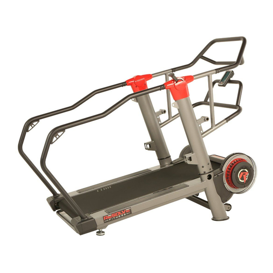
- Page 1 R1 Sled Treadmill 6040.2-100219...
- Page 2 PLEASE DO NOT RETURN THIS PRODUCT TO THE STORE. STOP. Contact customer service if you have any questions regarding assembly or proper operation of the machine. Email us at: Service@paradigmhw.com Or call us at: 1-844-641-7923 Hours: 8:00 am to 5:00 pm (PST) Monday thru Friday...
-
Page 3: Table Of Contents
TABLE OF CONTENT SERVICE ---------------------------------------------------------------------- 2 LABEL PLACEMENT ------------------------------------------------------- 3 IMPORTANT SAFETY GUIDELINES ---------------------------------- OVERVIEW DRAWING ---------------------------------------------------- 6 PARTS LIST ------------------------------------------------------------------ 7 HARDWARE & TOOL LIST----------------------------------------------- ASSEMBLY ------------------------------------------------------------------- 10 CONSOLE ------------------------------------------------------------------ 22 ADJUSTMENTS ------------------------------------------------------------ TRANSPORTING & STORAGE ---------------------------------------- MAINTENANCE & TROUBLESHOOTING -------------------------- WARRANTY ------------------------------------------------------------------ 28 PARTS REQUEST FORM ------------------------------------------------... -
Page 4: Service
SERVICE IMPORTANT: FOR NORTH AMERICA ONLY For damaged or defective product, questions, replacement parts or any other service support, please contact our customer service department by the below methods: For The Best Service, please Email: service@paradigmhw.com Response Time: 1-2 Business Days Emailing us with the information above will be the best method to receive a response during peak business hours Website:... -
Page 5: Label Placement
LABEL PLACEMENT... -
Page 6: Important Safety Guidelines
IMPORTANT SAFETY GUIDELINES Basic precautions should always be followed, including the following safety instructions when using this treadmill: Read all instructions before using this treadmill. NOTE: Failure to follow these instructions may lead to personal injury and cause damage to the treadmill. WARNING: To reduce the risk of burns, fire, electric shock or injury to any persons, please read the following:... - Page 7 IMPORTANT SAFETY GUIDELINES Formatted: Indent: Left: -0", Hanging: Keep Dry - do not operate in a wet or moist condition. Save these 0.38", No bullets or numbering, Widow/Orphan control instructions. Formatted: Indent: Left: 0.38" Do not operate the treadmill near a blanket. Excessive heating can occur and Formatted: Indent: Left: 0.38"...
- Page 8 CAUTION: Risk of Injury to Persons –To Avoid Injury, use extreme caution Formatted: Font: 15 pt when stepping onto or off of moving the running belt. Read Instruction Manual Before Using. Formatted: Font: 15 pt Formatted: Normal, No bullets or numberi...
- Page 9 IMPORTANT SAFETY GUIDELINES Formatted: Normal, Indent: First line: 0", Left 0 ch, Right 0 ch WARNING: Before beginning any exercise program consult your physician. This is especially important for the persons who are over 35 years old or who have pre-existing health problems.
-
Page 10: Overview Drawing
OVERVIEW DRAWING... -
Page 11: Parts List
PARTS LIST Description Description Main Frame 39 Screw M6*15L Adjustable Foot Pad 40 Flat Washer M6*16*1.5 Running Deck 41 Spring Washer M6 Screw M8*125*45L 42 Break Spin Ring Nylon Nut M8 43 Break Spin Ring Shaft Flat Washer M10*38*3.0t 44 Break Spin Ring Front Running Belt Roller 45 Flat Washer M8*23*2.0T Rear Running Belt Roller... - Page 12 PARTS LIST Description Description 77 Upper Sensor Cable Right Rear Handlebar Cover 78 Console Lower Left Rear Cover 80 Plastic Mesh Cover Lower Right Rear Cover 81 Motor cover - top Rear Rail Plug LeftCover 82 Sticker CoverRear Rail Plug Right 83 Motor cover - up Step On Cover...
- Page 13 HARDWARE & TOOLS PACK (50) Screw M5x10L (51) Screw M6x12L (55) Screw M5x12L (52) Screw M10x25L 2PCS 4PCS 6PCS 8PCS (54) Screw M6x12L (53) Screw M8x16L (56) Flat Washer M10 4PCS 44PCS 8PCS 8mm Allen Wrench 1 PC Double Wrench 6mm Allen Wrench 1 PC 1 PC...
-
Page 14: Assembly
ASSEMBLY This Treadmill weights more than 44 lbs., two people are required for the assembly of this treadmill. WARNING: Part 66 and Part 1 are connected by part 48 when pulled out of the box. Do NOT pull the piece apart from each other. - Page 15 ASSEMBLY Tool: 6mm Allen Wrench 1 PC Step 2 2a. Connecting the Sensor Cable: Connect the Lower Sensor Cable (31) to the Middle Sensor Cable (67). See Fig. B 2b. Installing the Left Upright Post: SLOWLY slide the Left Upright Post (65) onto the Main Frame (1).
- Page 16 ASSEMBLY Tool: 6mm Allen Wrench Double Wrench 1 PC 1 PC Step 3 3a. Installing the Right Right Rear HandlebarSide Handlebar: Attach the Right Right RearSide Handlebar (74) onto the Right Upright Post (66) and the Main Frame (1). Tighten the Right Right Rear HandlebarSide Handlebar (74) to the Right Upright Post (66) with...
- Page 17 ASSEMBLY Tool: 5mm Allen Wrench 1 PC Step 4 4a. Installing the Cover : Attach the Right Covers Rear Handlebar Cover 1 (9190) & Right Rear Handlebar Cover 2 (9091) onto the Right HSide Handlebar (74) and tighten with two Screws (54) using the 5mm Allen Wrench provided.
- Page 18 ASSEMBLY Tool: 4mm Allen Wrench 1 PC Fig. D Step 5 5a. Installing the Right CoverRear Rail Plug: Attach the Right Cover Rear Rail Plug (95) onto the rear of Right side of the Main Frame (1). Tighten with three Screws (55) using the 4mm Allen Wrench provided.
- Page 19 ASSEMBLY Tool: Double Wrench 6mm Allen Wrench 1 PC 1 PC Step 6 6a. Installing the Left Right Rear HandlebarSide Handlebar: Attach the Left Right RearSide Handlebar (73) onto the Left Upright Post (65) and the Main Frame (1). Tighten the Left Right Rear HandlebarSide Handlebar (73) to the Left Upright Post (65) with...
- Page 20 ASSEMBLY Tool: Fig. E 5mm Allen Wrench 1 PC Step 7 7a. Installing the Left Rear Handlebar Covers : Attach the Left Covers Rear Handlebar Cover 1 (9188) & Left Rear Handlebar Cover 2 (9089) onto the Left HSide Handlebar (73) and tighten with two Screws (54) using the 5mm Allen Wrench provided.
- Page 21 ASSEMBLY Tool: 4mm Allen Wrench 1 PC Fig. F Step 8 8a. Installing the Left CoverRear Rail Plug: Attach the Left Cover Rear Rail Plug (94) onto the rear of left side of the Main Frame (1). Tighten with three Screws (55) using the 4mm Allen Wrench provided.
- Page 22 ASSEMBLY Tool: 6mm Allen Wrench 1 PC Step 9 9a. Installing the Front Upper Handlebar: Attach the Front Upper Handlebar (76) onto the Left Upright Posts (65) and Right Upright Posts (66) and tighten with twelve Screws (53) using the 6mm Allen Wrench provided.
- Page 23 ASSEMBLY Fig. G Step 10 10a. Connecting the Extension Wires : Connect the Upper Console Cable (77) from the HFront Lower Handlebar (75) toto the Middle Sensor Cable (67) from the Left Upright Post (65). See Fig...
- Page 24 ASSEMBLY Tool: 6mm Allen Wrench 1 PC Fig. H Step 11 11a. Installing the Front Lower Console Bar: Attach the Front Lower Console Bar (75) onto the both the Left Upright Post (65) and Right Upright Post (66). Tighten with twelve Screws (53) using the 6mm Allen Wrench provided.
- Page 25 ASSEMBLY Tool: Screwdriver 1 PC Fig. I Fig. J Step 12 12a. Connecting the Console Wire: Connect the Upper Sensor Cable (77) to the black block at the back of the Console (78). See Fig. I. 12b. Console Installation: Insert the wires into the hole of the Front Lower Console Bar (75) and attach the Console (78) to the console plate on the...
-
Page 26: Console
CONSOLE TIME:Displays the elapsed time of the workout. SPEED:Displays the current running speed of the workout. DISTANCE:Displays the total distance run during the workout. CALORIES:Displays the calories burned during the workout. NOTE: The value of calories is only an estimate. This value should be used to track progress between workout. - Page 27 CONSOLE BUTTON FUNTIONS [ MODE ]: 1. Before starting a workout, this button allows you set up a goal workout. a. Press the MODE button once to make the TIME display flash. A TIME goal can be set up by using the arrows to set a TIME goal value. b.
- Page 28 CONSOLE WORKOUT GOAL FUNTIONS 1. TIME COUNTDOWN: a. The preset value is 0:00. b. The setting range is 0:00~99:00. c. Each increase/ decrease is 1:00. 2. DISTANCE COUNTDOWN: a. The preset value is 0.0. b. The setting range is 0.0~999.0. c.
-
Page 29: Adjustments
ADJUSTMENT Resistance Adjustment: 1. Use the resistance level to adjust the resistance level of the workout. If you want to increase the resistance, push the lever forward; if you want to decrease the resistance, pull the level backward. 2. Resistance Level 1allows the treadmill to go faster than level 7. 3. -
Page 30: Transporting & Storage
TRANSPORTING & STORAGE Transporting the Treadmill: 1. Hold the Handlebar and lift up the machine until the wheels make contact with the floor. 2. Push or pull the unit to the desired location, then gently lower the machine until it makes contact with the ground. -
Page 31: Maintenance & Troubleshooting
MAINTENANCE & TROUBLESHOOTING MAINTENANCE SCHEDULE MAINTENANCE SCHEDULE ACTION FREQUENCY ACTION FREQUENCY Clean entire machine using water and a mild soap or other Matrix approved solution (cleaning agents DAILY Clean entire machine using water and a mild soap should be alcohol and ammonia free). or other Matrix approved solution (cleaning agents DAILY Check harness for wear and secure connections. -
Page 32: Warranty
WARRANTY MANUFACTURER’S LIMITED WARRANTY Paradigm Health & Wellness warrants to the original purchaser that this product is free from defects in material and workmanship when used for the purpose intended, under the conditions that it has been installed and operated in accordance with Paradigm’s Owner’s Manual. -
Page 33: Parts Request Form
PARTS REQUEST FORM Paradigm Health & Wellness, Inc. EMAIL THIS FORM WITH YOUR RECEIPT OF PURCHASE TO Service@paradigmhw.com NAME:_____________________________________________________________________________________ ADDRESS:__________________________________________________________________________________ CITY:________________________ STATE:_____________ ZIP:_______________________________________ TELEPHONE: (Day)__________________________________________________________________________ (Night)_________________________________________________________________________ SERIAL#:___________________________________________________________________________________ MODEL#:___________________________________________________________________________________ PURCHASE DATE:___________________________________________________________________________ PLACE OF PURCHASE:_______________________________________________________________________ PART # DESCRIPTION “YOUR ORDER WILL BE PROCESSED WITHIN 3 BUSINESS DAYS” * This form can also be faxed in Fax #: 626-810-2166...
Need help?
Do you have a question about the R1 Sled Treadmill and is the answer not in the manual?
Questions and answers