Table of Contents
Advertisement
Quick Links
Advertisement
Table of Contents

Related Manuals for NewTek TriCaster TC Mini TCMI4KUHD

Summary of Contents for NewTek TriCaster TC Mini TCMI4KUHD
- Page 2 Revised – Oct. 28, 2019 Trademarks: NewTek, NewTek VMC, NewTek VMC1, NewTek VMC1 IN, NewTek VMC1 OUT, NewTek NC1, NewTek NC1 IN, NewTek NC1 I/O, NewTek NC1 I/O IP, TriCaster, TriCaster TC1, TriCaster Advanced Edition, TriCaster XD, TriCaster 8000, TriCaster TCXD8000, TCXD8000,...
-
Page 3: Table Of Contents
Table of Contents SECTION 1 QUICKSTART ..........................4 SECTION 2 INTRODUCTION AND SETUP ..................... 7 2.1 Overview ....................................7 2.2 Making Connections ................................7 2.3 Configuring TriCaster ................................8 2.4 Web Configuration ................................. 9 2.4.1 Device Details ................................10 2.4.2 Device and Channel Name ............................10 2.4.3 Audio .................................... -
Page 4: Section 1 Quickstart
After completing this section, you’ll be ready to begin using your device. This document briefly describes how to prepare your new NewTek™ TCMI4KUHD device for use. Please note that more detailed information is provided in the next chapter. - Page 5 Hint: Connected TCMI4KUHD devices appear the menu as TCMI4KUHD – (unit serial number) > Channel 1. 4. Select TCMI4KUHD – (serial number) > Channel 1 as the source for the Switcher input. 5. Then click the Device Webpage button that appears at right upon connection to open TCMI4KUHD’s configuration webpage in a web browser.
- Page 6 Hint: Should you set a custom password and then forget it, you can reset the device to factory defaults using the Factory Reset process. Conclusion This completes the initial setup of your NewTek™ TCMI4KUHD. You should see its output displayed on Studio Monitor. The sections that follow provide more in-depth coverage of features and options.
-
Page 7: Section 2 Introduction And Setup
OVERVIEW Thank you for purchasing this NewTek™ product. NewTek is extremely proud of its record of innovation, and its commitment to excellence in design, manufacture, and superb product support. -
Page 8: Configuring Tricaster
RJ-45 ports marked NDI 1-4 on TriCaster TC Mini’s rear. Hint: The input module boots as soon as this connection is made if TriCaster is powered up. At this point, the NewTek logo will illuminate. (If this does not happen, check your connections and retry.) 2. -
Page 9: Web Configuration
WEB CONFIGURATION Sometimes, though, you will want to access your input module’s local settings, perhaps to configure login credentials, update firmware, etc. These features are made available by means of the device’s local configuration webpage, which you can access directly from TriCaster. Note: You may occasionally find it necessary to delete cached files (sometimes referred to as the browser’s “history”) before the display refreshes to properly show some recent change. -
Page 10: Device Details
FIGURE 10 At this point, the TCMI4KUHD configuration webpage will be displayed (Figure 10). DEVICE DETAILS 2.4.1 FIGURE 11 The uppermost section of the Device Setting tab on the web page shows Audio/Video format details, the current bitrate and the unit’s serial number. These values are automatically detected, and are not editable. DEVICE AND CHANNEL NAME 2.4.2 FIGURE 12... -
Page 11: Audio
These names are editable, allowing you a convenient way to identify the output of specific units to downstream NDI-enabled devices and systems. Hint: The default name includes the unit serial number, which is also provided on a sticker on the chassis to help you identify a specific device. -
Page 12: Network Settings
NETWORK SETTINGS FIGURE 16 Just beneath the Reset, Reboot and Restore controls in the Device Settings tab is a control group labeled Network Settings, which is host to NDI Connection, Ethernet, and Local –Link settings. NDI CONNECTION 2.5.1 FIGURE 17 ONNECTION EFAULT OR ULTICAST... -
Page 13: Ethernet
• In addition, we strongly recommend that all network switches be of the ‘managed’ type (see the sidebar “Managed vs. Un-managed”). ETHERNET 2.5.2 FIGURE 18 Controls in this section will be quite familiar to anyone who has connected a computer or mobile device to a network and require little explanation. -
Page 14: Tally
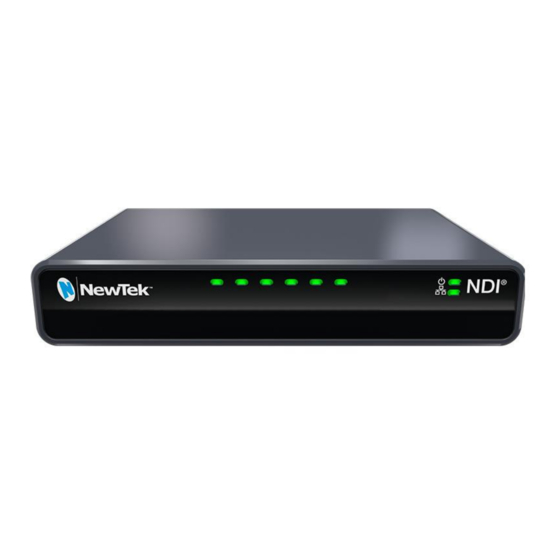
TALLY FIGURE 19 Your TCMI4KUHD unit provides ‘tally’ notification from TriCaster. Specifically, a row of LEDs will light up in red or green to tell you when video output from the device is visible on the Program output or Preview row of a video switcher respectively, as illustrated above. -
Page 15: Credits And Trademarks
Cooper, Ryan Hansberger, Shawn Wisniewski, Steve Bowie, Troy Stevenson TRADEMARKS NewTek, NewTek VMC, NewTek VMC1, NewTek VMC1 IN, NewTek VMC1 OUT, NewTek NC1, NewTek NC1 IN, NewTek NC1 I/O, NewTek NC1 I/O IP, TriCaster, TriCaster TC1, TriCaster Advanced Edition, TriCaster XD, TriCaster 8000, TriCaster TCXD8000, TCXD8000, TriCaster...
Need help?
Do you have a question about the TriCaster TC Mini TCMI4KUHD and is the answer not in the manual?
Questions and answers