
Subscribe to Our Youtube Channel
Related Manuals for CRKITS CRK-10A


Summary of Contents for CRKITS CRK-10A
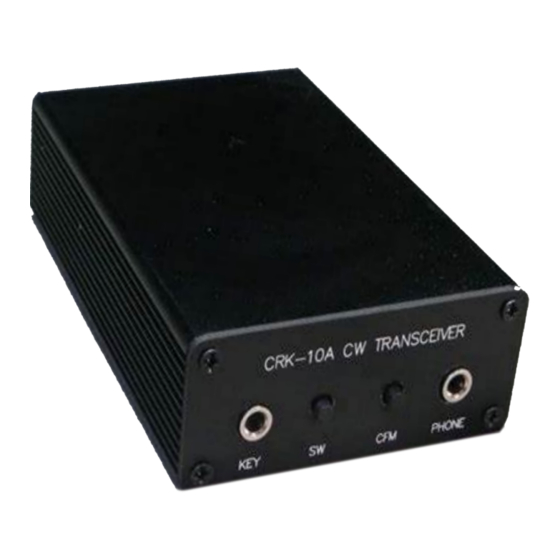
- Page 1 CRK-10A CW Transceiver Kit Manual Rev. A CRKITS.COM May 19, 2013 Change History: May 19, 2013: Initial release - Rev. A...
- Page 2 Thanks for choosing CRK-10A CW Transceiver kit. It is a great one-evening project to provide you pure fun of both kit building and QRP operation. CRK-10A design is inspired by RockMite from Small Wonder Labs. RockMite was introduced to China years ago by BD6CR/4. BD4RG, the designer of HB-1A and HB-1B, improved the design by rewriting the firmware, increasing RF power output, and smoothing the keying.
- Page 3 Follow the part list below to do parts inventory first. Please note the difference between 30 meter kit and 40 meter kit. If there are any missing parts or questions, please contact your local distributor or CRKITS.COM directly by email at rongxh@gmail.com. Item...
- Page 4 IC, balanced mixer NE602 IC, op amp NE5532 IC, MCU 12F629, programmed IC3 Transistor 2N3904 Q1, Q2 Transistor 2N3906 Transistor 2N4401 Field Effect Transistor 1 J309 Power Amp. transistor 1 2SC1162 Inductor, fixed 10 uH Inductor, toroid T37-2, red L2 (10 turns), L3 (12 turns) Enamel wire 0.4m 0.38mm diameter...
- Page 5 Step by Step Building It takes about 2.5 hours to build and align the kit. You will need to prepare basic soldering and alignment tools to be able to build this kit. Step 1: Resistors Stuff all the resistors, solder and cut the extra leads. If you are not sure about the color codes, you can use an ohm meter to verify value before you solder.
- Page 6 Step 2: Diodes Stuff all the diodes. Note for the polarity. Solder and cut the extra leads. D2, D4, D5~D9 1N4148, glass body • 1N5817, black • 1N4755A, silver •...
- Page 7 Step 3: Ceramic capacitors, regulator IC and IC sockets Install all the 0.01 uF (103) and 0.1 uF (104) ceramic capacitors. C25 is only required for 30 meter kit. C3, C12~C14, C17, C19, C22 0.01 uF • 0.01 uF (30 m) •...
- Page 8 Step 4: Audio filter and amplifier Install Q3 (J309). Note for static sensitive part. Handle with care. Install C32 (100 uF 25 V) and C33 (10 uF 25 V). Note for polarity. Install C30 and C31 (polyester film 0.01 uF, 2A103J). Install C21 (100 p).
- Page 9 Step 5: MCU Install KEY jack Install SW Install C26 (33 p), C34 (100 p) and C35 (100 p) Insert IC3 (12F629). Note for orientation. Test: Apply power supply, and connect a headphone to PHONE jack. Press SW1 to hear Morse code.
- Page 10 Step 6: Local Oscillator Install C23 (9-50 pF), C24 (9-50 pF) Install Q1 (2N3904), Q4 (2N3906) Install crystal X3 (Case grounding pad is reserved, but not used) Install C1 (100 uF 25V). Note for polarity. Install C4 (100 p), C15 (100 p), C16 (100 p) Install SW1 Test: Apply power supply.
- Page 11 Step 7: Transmitter and Board Complete Follow the picture to wind 10 turns for L2 and 12 turns for L3. They are parts of the low-pass filter to purify the transmitter output. Scratch the enamel of wire endings and tin them well. Install Q2 (2N3904), Q5 (2N4401).
- Page 12 Note: Schematic here is only for 40 m. Refer to the schematic for 30 m at the end of this document. Test: Apply power supply, connect a dummy load of 50 ohm at least 5 watts. Place a SSB/CW receiver nearby and tune to around the frequency of X1, X2 or X3. Press SW to monitor the Morse code by leakage from dummy load.
- Page 13 Step 8: Thermal Pad / Insulator Split the panel board to two halves. Cut thermal pad about 3~4 mm as shown. Follow the pictures to stick the thermal pad to the inner side of the rear panel, and fix Q6 (2SC1162) to the rear panel by M3 screw and nut.
- Page 14 It is preferred that you have a power supply of 12~13.8V with short circuit protection. Connect the power supply to the CRK-10A to see if it works. The overall receive current should be about 15 Disconnect the power supply, connect a headphone, a paddle and an antenna or a 50 ohm dummy load, then connect the power supply again, you should hear dot dash.
- Page 15 Step 10 : Final Assembly Follow the pictures to slide the board to the case and finish the final assembly. Note that the bottom side of the case has two lines, while the top side is flat. Fix the rear panel and front panel by the 8 pcs pan head M2.5 panel screws. Stick four rubber feet on the bottom side of the case.
- Page 16 Operation If an effective antenna is used, 3 watt RF power is good enough to make others heard. Although it is a QRP radio, you are encouraged to call CQ to be able to make more successful QSO's. Luckily you can use the push button to automatically call CQ. Sometimes, you can hear a station well, but no matter how you call him, he just cannot hear you.
- Page 17 Morse code BUG, and the radio will be chosen to work in bug simulation mode. In bug simulation mode, dots will be sent automatically by the MCU and dashes will be sent manually. Note that the keyer does not actually support mechanical bug key. Adding /QRP You can choose to add /QRP or not in auto CQ.
- Page 18 Theory of Operation The MCU servers a controller and a keyer. It controls RX/TX switch, including receiver mute and transmit frequency shift. As a keyer, it reads the key input, keys the transmitter to send the signal and generate side tone as well. The receiver is a typical NE602 direction conversion receiver, with the exception that it only receives one frequency, so a 2-pole crystal filter is added in the front-end to block most of the broadcast interference out.
- Page 19 Schematic of 30 meter version Troubleshooting If the receive current is much higher than 15 mA, it means the circuit has issue. Inspect all the components to make sure they are installed properly, especially the components with polarity such as electrolytic capacitors, and IC orientation. If all the components are installed properly but the symptom persists, most likely it is because of the PCB short.
Need help?
Do you have a question about the CRK-10A and is the answer not in the manual?
Questions and answers