
Related Manuals for Grace Industries Grace-Watch


Summary of Contents for Grace Industries Grace-Watch
- Page 1 Grace-Watch ® Advanced Safety Monitoring System User’s Information Grace Industries, Inc. Patent Protected US 7,538,666 ® Grace-Watch 3.05.0100...
- Page 2 Protecting Personnel With advanced hardware and software features, ® Grace-Watch systems provide an unbeatable method of protecting your personnel at any facility while simplifying the Accountability responsibilities of monitoring personnel. 04-2020...
-
Page 3: Table Of Contents
Getting Started Table of Contents Introduction Location Setup Minimum Computer Requirements GPS Device Mapping Installing USB Drivers from FTDI Setting Audio Alarms Connecting the MX900-H Configuring Notifications Installing System Software Save and Exit Configuration Operation Setup Start an Incident Setting the System ID Monitoring Screen System Settings User Status Images... -
Page 4: Introduction
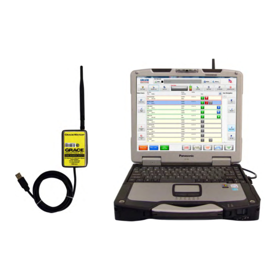
Introduction MX900-H Grace Worker Worn Transceiver Man-Down Devices Thank you for purchasing a Grace Industries Accountability System ® ® Grace-Watch Advanced Safety Monitoring System uses Grace-Watch Software and the components listed below to provide complete accountability for your personnel. System Components ... - Page 5 In, or Roll Call Signal with a simple button press All personnel within range at the facility are automatically populated in the Grace-Watch software and are sorted in real-time based on priority, with Fall-Alarm being the highest priority When an Alarm, Call-Back, Report-In, or Roll Call signal is ...
- Page 6 MX900-H Transceiver Receives and processes radio signals from Grace worker worn devices and transmits Call-Back, Report-In, and Roll Call signals to those devices Monitors PC communications through the USB port and goes into Alarm if the communications fail at any time External Antennas may also be used as ...
-
Page 7: Minimum Computer Requirements
Minimum Computer Requirements for Grace-Watch Systems Processor: 1 GHz 32-bit (x86) (2Ghz or faster processor recommended) Operating Systems: Windows 7, 8, 10 (32-bit and 64-bit) Administrative rights required RAM: Monitor: 1024×768 (Touchscreen Recommended) ... -
Page 8: Installing Usb Drivers From Ftdi
USB Drivers must be installed on your PC before MX900-H can be recognized on the PC. FTDI is the world leader in USB development and supplies robust USB communication and functionality in our product. ® Grace-Watch Installation Flash Drive: Insert the Installation USB flash drive. ... -
Page 9: Connecting The Mx900-H
Connecting the MX900-H Set the Laptop on a flat, level surface Attach the MX900-H to Laptop using the duallock Velcro. Plug the MX900-H USB cable into the Laptop Computer This will connect and power up the MX900-H ... -
Page 10: Installing System Software
When prompted, select Open folder to view files (or manually go to USB flash drive directory) and select GCLaunch.exe When you have the option, left-click the Install button for Grace-Watch Software. Follow the on screen prompts. ... - Page 11 Starting the Software Locate the Grace-Watch Icon on the Desktop and double click The software will start up and the Operation Setup Screen will appear Return to TOC...
-
Page 12: Operation Setup
The Operation Setup Screen Incident Name, Incident Number, and Time/Date are auto-filled Must Enter Incident Type and Position to Start an Incident Location Files May be Pre-Loaded to fill in Location Fields Automatically Utilities Bar Can be Shown or Hidden by Pressing Show Utilities Button ... - Page 13 This field contains the Incident date and time stamp of when the incident is started. If you return to the setup screen after the incident incident was started and is auto loaded by the Grace-Watch has started, the return to incident button replaces the start incident software when an incident is started.
- Page 14 This field allows the loading of pre-configured Incident Locations entry is available. Direct typing of the street suffix is also permitted. such as Grace Industries, Mercy Hospital, etc., and is an optional LOCATION CITY setting. The combobox drop down items contain the location files This field contains the incident address city such as Hermitage, New that are present on the hard drive of the computer.
- Page 15 This button starts the incident and displays the main monitor screen etc., and is an optional setting. The combobox drop down items can of the Grace-Watch Software. This is the main screen used when be customized in the configuration area so that easy entry is running an incident.
- Page 16 Utilities Bar Help Manual: Launches Grace-Watch Help Manual Program TPass: Program Worker Worn Device ID Numbers File Maintenance: Backup/Restore Grace-Watch Settings, Import/Export Names, Messages, Etc. Return to TOC...
- Page 17 Program Worker Worn Device ID Numbers Use the discover button while putting the device into alarm to learn the current settings of the device you want to change. Once discovered, enter the new device ID in the TPASS ID Program section ...
- Page 18 Configuration Enter the Configuration Area by pressing the Configure Button on Operation Setup Screen. There are 4 main areas as described below. INCIDENT SETUP The Incident Setup section allows the configuration of the drop down boxes on the Operation Setup screen. USER SETUP ...
- Page 19 Configuration Screen Return to TOC...
-
Page 20: Setting The System Id
Setting The System ID The first operation that should be performed is setting the proper System ID for the Grace-Watch System NOTE: System ID must match System ID of the worker worn devices for the units to be displayed and monitored Click the System Setup tab near the top of the screen to access ... - Page 21 System ID = 51 most significant digit->5 1<-least significant digit The System ID of the Grace-Watch Software sets the receive parameters for the MX900-H unit allowing reception of worker worn device messages from users within a block of 16 groups, 1-99 users per group plus 9 Micro Repeaters per group.
-
Page 22: System Settings
System Settings Dialog Return to TOC... - Page 23 System Settings On the System ID Tab, Set the System ID Leave Groups To Monitor Checkbox Checked. On the Aux IDs Tab, leave Enable Aux IDs unchecked. Leave No-Signal Setting to 15 Minutes Leave the Action and Clear Key Hold Times Set a .5 and 1 second ...
- Page 24 SYSTEM ID TAB \ SYSTEM ID ACTION KEY HOLD TIME This field sets the System ID for the Grace-Watch system. This field allows setting of the action key hold time required to perform a device command from the monitor screen.
-
Page 25: Configure Connections
Configure Connections RECEIVER TYPE Dropdown used to select type of receiver for the connection. BAUD RATE Dropdown used to select baud rate. Select 38400 when using the MXH. COM Port Dropdown used to select from available port numbers. ... -
Page 26: User Setup
User Setup Screen Press the User Setup Tab to Access the User Setup Area Return to TOC... -
Page 27: Create A Name File
Creating a Name File Press the Create a Name File Button to Access the Name File Creator Wizard Enter the File Name, e.g. Acme Iron Works Notice the System ID is set and cannot be changed from this screen ... - Page 28 Name File Return to TOC...
- Page 29 Setting the Active Name File The Name File just created must now be set to the Active Name File so that it is loaded when an incident is started Press the Choose Active Name File Button and select the file just created ...
- Page 30 Listing the Available User Titles Press the User Ranks Button to Edit User Title Enter a Title into the Create New Box and Press Add User Rank The Title Will Be Added to the Dialog Box on the Right Highlight a Title and Press Remove button to ...
- Page 31 Setting the User Divisions Press the User Divisions Button to Edit User Divisions Enter a Division into the Create New Box and Press Add User Division The Division Will Be Added to the Dialog Box on the Right Highlight a Division and Press Remove to ...
- Page 32 Setting the User Sub-Divisions Press the User Sub-Divisions Button to Edit User Sub-Divisions Enter a Sub-Division into the Create New Box and Press Add User Sub-Division The Entry Will Be Added to the Dialog Box on the Right Highlight an Entry on the right and Press ...
- Page 33 Setting the User Note Titles Press the Note Titles Button to Edit User Note Titles Enter the Titles for Each User Notes Tab to be displayed on the User Profile Screen Press Done when Finished Return to TOC...
- Page 34 Editing the Name File Information Press the Edit Name File Button from the User Setup Screen to Access the Edit Names Dialog Double-Click a user name or Highlight the User and Press the Edit Button to view the User Profile Dialog Enter Information and Press Save to Save the Changes ...
- Page 35 Editing the User Profile Enter in User Name, Title, and Personal Information fields as needed Select the device type to be displayed. Add a User Picture if Desired - for best results use a picture size is 75 by 100 pixels ...
- Page 36 Adding a User Picture Double-click the Picture image or press the Picture button from the User Profile Screen Highlight the Picture Desired and press select Highlighted Picture Press the Accept Button to load the picture into the profile ...
- Page 37 Editing User Notes Click on Each Note Tab to Reveal the Memo Area for Each User Note Memo Enter information into each note memo Press Save when Complete Return to TOC...
- Page 38 Adding a User to a Name File Users May Be Added to the Name File from the Edit Name File List screen by pressing Add User Enter the Group and User ID for the User desired Press Default to automatically create a default name entry or ...
- Page 39 Deleting a User from a Name File Users May Be deleted from the Name File from the Edit Name File List screen by pressing Delete User A Confirmation Window will appear to insure deletion is desired Press Yes to delete the Name ...
- Page 40 Deleting a Name File Name Files May Be Deleted from the System using the Delete Name File Button on the User Setup Screen Press the Delete File Button and select the file to be deleted Press Yes to confirm and delete the file ...
-
Page 41: Prepared To Monitor Users
Prepared to Monitor Users After completing the above procedures, the system is able to monitor the worker worn devices assigned to users The five critical steps to prepare the software for use with worker worn devices and the MX900-H are: Set the System ID Set the Receiver Type to MX900-H Set the Com Port for the MX900-H Communications... -
Page 42: Configuring Incident Settings
Configuring Incident Settings Press the Incident Settings Tab from the Configuration Area There are two basic sub-categories: Incident Data Settings Incident Location Settings Press Each Button to Access the area to configure Return to TOC... - Page 43 Highlight a Type and Press Make Default to Make the Selected Type the Default Check Load Default Type to Load this Type as the Default on the Operation Setup Screen when Grace-Watch is started Press Done when finished Return to TOC...
- Page 44 Highlight a Position and Press Make Default to Make the Selected Position the Default Check Load Default Position to Load this Position as the Default on the Operation Setup Screen when Grace-Watch is started Press Done when finished Return to TOC...
- Page 45 Highlight a Shift and Press Make Default to Make the Selected Shift the Default Check Load Default Shift to Load this Shift as the Default on the Operation Setup Screen when Grace-Watch is started Press Done when finished Return to TOC...
- Page 46 Make the Selected Plan Number the Default Check Load Default Checkbox to Load this Plan Number as the Default on the operation setup screen when Grace-Watch is started Enter the Custom Label to use for Plan Numbers, e.g. Box Alarm, etc.
- Page 47 Highlight a Commander and Press Make Default to Make the Selected Commander the Default Check Load Default Commander to Load this Commander as the Default on the Operation Setup Screen when Grace-Watch is started Press Done when finished Return to TOC...
- Page 48 to Make the Selected Run Card the Default Check Load Default Run Card to Load this Run Card as the Default on the Operation Setup Screen when Grace-Watch is started Press Done when finished Return to TOC...
-
Page 49: Location Setup
Make the Selected Location the Default Check Load Default Location to Load this Location on the Operation Setup Screen when Grace-Watch is started Press Done when finished The number of Location files possible is virtually unlimited – limited by available hard drive space –... - Page 50 Creating a Location Enter all fields including name, description and address fields Press Load Picture to add a picture of the location Press Done when finished *This Feature is NOT Available for International Use with MX900-H Transceiver Return to TOC...
- Page 51 Adding a Location Picture Select The picture desired from the existing pictures box Press Select Highlighted Picture Press Accept to accept the picture Press Cancel to cancel the action Return to TOC...
- Page 52 Editing an Existing Location Select a Location from the list on the Edit Locations Dialog and press the Edit Location button Change any fields (except the name) and picture desired Press Done when finished Return to TOC...
- Page 53 Locator Image Mapping *This Feature is NOT Available for International Use with MX900-H Transceiver Locator Image Mapping provides the ability to associate locators to points on an image. Images would typically be maps of your establishment where locators are positioned. The configuration screen can be invoked by editing a location ...
- Page 54 Locator Image Mapping *This Feature is NOT Available for International Use with MX900-H Transceiver Return to TOC...
- Page 55 Locator Image Mapping *This Feature is NOT Available for International Use with MX900-H Transceiver Add Map Button The add map button allows you to load a new image by browsing the file system. A copy of the loaded image is saved to the configuration folder. The original is not disturbed.
- Page 56 Locator Image Mapping *This Feature is NOT Available for International Use with MX900-H Transceiver To map a location point, click and drag the desired locator to a point on the map and drop it. The mapping details screen will pop up. ...
- Page 57 Locator Image Mapping *This Feature is NOT Available for International Use with MX900-H Transceiver Design Time Parameters These options describe how the locator will appear on an image during configuration. Include Locator Name This will place the Location Point name next to the desired image on the map. ...
- Page 58 Locator Image Mapping *This Feature is NOT Available for International Use with MX900-H Transceiver Return to TOC...
- Page 59 Locator Image Mapping *This Feature is NOT Available for International Use with MX900-H Transceiver Run Time Screen The image section of the screen will display the selected users location as described in setup. Other locations that have been mapped will also display. Selecting the mapped user or any other location on the map will display a list ...
-
Page 60: Gps Device Mapping
GPS Device Mapping When using GPS Enabled worker worn devices, you can view the device’s actual location on a real-time map. Units that have acquired a GPS lock will appear on the main incident screen with the GPS symbol next to the device type. Double-clicking the GPS symbol will invoke the map. - Page 61 GPS Device Mapping Base Maps The mapping feature allows you to choose your map type. Several base map options are provided, including imagery and street views from Esri, OpenStreetMaps and Bing Maps. The mapping functions use caching so that previously loaded maps are also available offline. Caching an area can be achieved by viewing the location at various zoom levels or by using the built-in caching tool that works with the Esri style base maps.
- Page 62 GPS Device Mapping Layer Management Screenshot Return to TOC...
- Page 63 GPS Device Mapping Screenshot showing local lake marked with an imported Esri Shapefile layer Return to TOC...
- Page 64 GPS Device Mapping Static Markers You can manually mark any location on the map using Static Markers. There are hundreds of predefined images included or you can import your own images to be used. Static Markers are saved when the program closes and will automatically be placed every time you start an incident and open the map tool.
- Page 65 GPS Device Mapping Screenshot showing 2 static markers used to mark a parking area and wooded area. Return to TOC...
- Page 66 GPS Device Mapping Incident Device Live Markers During an incident, GPS enabled devices will appear on the map using the symbols shown below and will depend on the status of the device. Non-Selected devices will display in the reverse colors of the selected device. The GPS fix quality will be seen as a semi-transparent radius around the marker that will vary in size depending on the quality of the signal.
- Page 67 GPS Device Mapping Screenshot showing Selected and Non-Selected Device Markers. Notice the Selected Marker has the GPS Fix Radius. Return to TOC...
- Page 68 GPS Device Mapping Configuration All of the features described above are also available in configuration mode before an Incident is started. Here you can preconfigure available maps, load layers and place static markers so they are available when an incident is started. You can also limit the functionality that will be available when an incident is started.
- Page 69 Depending on the internet connection speed, this may take a considerable amount of time to complete. It is highly recommended the map caching setup be completed before using the Grace-Watch system. Example: Caching the maximum cache area (approximately 250 sq. miles) with a 50MB/s connection will take approximately 60 minutes.
- Page 70 This allows you to define these items in configuration mode so that layers and static markers are projected on to the map but the Grace-Watch user cannot modify them. You can also change the look of the mapping screens by using the Application Skin drop down and selecting an alternate skin.
- Page 71 GPS Device Mapping Configure / Base Maps Here you can choose the Base Maps that will be available to the Grace-Watch. When choosing any of the Bing map types, the Bing Maps API Key is required. The Clear Map Cache button is available so you can delete all of the map tiles that are currently downloaded and available to the application.
- Page 72 Creating a Location Enter all fields including name, description and address fields Press Load Picture to add a picture of the location Press Done when finished Manage Locators and Plot Locators To Maps are only used when using Grace Locators.
- Page 73 Locator Configuration *This Feature is NOT Available for International Use with MX900-H Transceiver For each Grace Locator used, enter name and description information in the row that corresponds to the locator ID. Locators can be associated to GPS Coordinates by entering the latitude ...
- Page 74 GPS Lookup Use the navigation tools to find the desired location on the map. Use the mouse to choose the location on the map. The latitude and longitude fields will be populated. Press ok and the locator fields will be populated with these values. ...
- Page 75 Highlight a Prefix and Press Make Default to Make the Prefix the Default Check Load Default Prefix to load this Prefix as the Default on the Operation Setup Screen when Grace-Watch is started Press Done when finished Return to TOC...
- Page 76 Highlight a Street and Press Make Default to Make the Street the Default Check Load Default Street to load this Street as the Default on the Operation Setup Screen when Grace-Watch is started Press Done when finished Return to TOC...
- Page 77 Highlight a Suffix and Press Make Default to Make the Suffix the Default Check Load Default Suffix to load this Suffix as the Default on the Operation Setup Screen when Grace-Watch is started Press Done when finished Return to TOC...
- Page 78 Highlight a City and Press Make Default to Make the City the Default Check Load Default City to load this City as the Default on the Operation Setup Screen when Grace-Watch is started Press Done when finished Return to TOC...
- Page 79 Highlight a State and Press Make Default to Make the State the Default Check Load Default State to load this State as the Default on the Operation Setup Screen when Grace-Watch is started Press Done when finished Return to TOC...
- Page 80 Highlight a Zip Code and Press Make Default to Make the Zip Code the Default Check Load Default Zip Code to load this Zip Code as the Default on the Operation Setup Screen when Grace-Watch is started Press Done when finished Return to TOC...
- Page 81 Highlight a Country and Press Make Default to Make the Country the Default Check Load Default Country to load this Country as the Default on the Operation Setup Screen when Grace-Watch is started Press Done when finished Return to TOC...
- Page 82 Configuring General Setup Return to TOC...
- Page 83 Changing the Custom Logo Select Browse from the General settings Tab Select a picture from the list and press Select Highlighted Picture Logo graphic files must be placed in <Program Folder>\logos Press Accept to Accept the new picture or Cancel to cancel the action ...
-
Page 84: Setting Audio Alarms
Custom audio files can be used by creating a sound file in the .mid, .wav or .mp3 format and placing a copy of it into the ‘Alarms’ folder in the user configuration folder where the application is installed. Ex: C:\ProgramData\Grace Industries\Grace-Watch\Alarms Return to TOC... - Page 85 Configuration Protection Check Show Warning Message on Entry to display a warning message when entering the configuration screens. Check Log Date and Time to force the system to log a timestamp when configuration changes are made. Located in Program Data/Logs. Check Password Protect and provide a password to force a login screen ...
- Page 86 Add canned messages desired to all 120 locations SuperCELL and WorkForce WF2 currently support 16 canned messages Grace-Watch supports 80 canned messages to account for future SuperCELL and WorkForce Development Each canned message may contain 16 ...
- Page 87 Email/SMS Notifications A notification is the ability of the system to be configured to respond to a specific event by sending an email, text message or Grace system message to one or more recipients. Return to TOC...
-
Page 88: Configuring Notifications
Configuring Notifications Connections Choose Configuration/General Setup/Notifications. The fourth tab over is where you will setup your connections to SMTP servers. There are two separate setups. One for Email and one for SMS Messages. This is for flexibility. These setups could be the same. - Page 89 Configuring Notifications Triggers Return to TOC...
- Page 90 Configuring Notifications Triggers Continued Select the fifth tab on the notification configuration Time Range screen to setup triggers. Triggers are the events that Enter the time range that this trigger will be active. take place to cause a notification. This is where you Providing the same time for upper and lower ranges describe the conditions that must occur to ‘trigger’...
- Page 91 Configuring Notifications Email Return to TOC...
- Page 92 Configuring Notifications Email Continued Select the first tab on the notification configuration Subject screen to setup an email. Enter a short generic description about the email. This is the email template that is used when a Message notification is triggered by the system.
- Page 93 Configuring Notifications SMS Message Select the second tab on the notification configuration screen to setup an SMS Message The fields for an SMS Message are the same as the fields for an email with the exception of ‘Mobile #’ and ‘Carrier’.
- Page 94 Configuring Notifications Grace Message Select the third tab on the notification configuration screen to setup a Grace Message notification. Field Descriptions Use Grace Message Notifications You must check this box to activate canned message notification. Log To Incident ...
- Page 95 Incident and Data management Return to TOC...
-
Page 96: Save And Exit Configuration
Done with Configuration EXIT CONFIGURATION BUTTON This button prompts the user to save changes. The user will be prompted with yes, no and cancel options. Choose “yes” to save changes, “no” to discard changes and “cancel” to remain in the configuration screen. After choosing “yes” or “no” the user will be returned to the Operations screen. - Page 97 The Operation Setup Screen Return to TOC...
-
Page 98: Start An Incident
Starting an Incident Once the Configuration is complete, you are ready to start an Incident The only fields that need populated are the Incident Type and Position. These fields MUST be populated to access the Start Incident Button and start an incident. -
Page 99: Monitoring Screen
The Monitoring Screen Return to TOC... - Page 100 The Monitoring Screen The Main Monitoring Screen has Four Major Areas: The Main Bar (also contains the Alarm Box) The Grace Messaging Bar The Monitoring Window with users monitored, a Selection Bar and Navigation Bar The Action Bar with action buttons and clear buttons Note that users are “grayed out”...
- Page 101 In addition, a flashing ALARM Users that check in to the Grace-Watch system message will be displayed in the alarm status box. light up with a light yellow background and the active Once a user’s alarm has been reset, the alarm status...
- Page 102 These logs are saved in an incident file and can be viewed at a later date using the Grace-Watch Incident Viewer. The logs can be viewed at any time by pressing the appropriate buttons on the monitor main tool bar.
- Page 103 Communications Fault If the MX900-H does not communicate at least once every 2 seconds with the computer, a Communication Fault will appear in the Alarm Status Box. The Communication Fault will clear automatically when communication is restored between the computer and the MX900-H. Return to TOC...
- Page 104 Monitor Screen with Active Users Return to TOC...
- Page 105 Monitor Screen with Active Users Users that are active will “light up” in the Status column shown on the right Users are sorted real-time based on status Alarm is the highest, followed by Abandon, Call-Back, Report-In, Roll Call, ...
- Page 106 User Information Bar Each user present on the system has a user information bar displaying the user’s Name, Group and User ID, Rank, Assignment, Online Time and status images User status images reflect the various functions of the user including Alarm, No ...
- Page 107 Viewing a User Profile The User Profile may be quickly viewed from the monitor screen by clicking on that user’s name column in the user’s information bar When complete, press the Done Button to close Return to TOC...
- Page 108 The User Assignment Dialog Select the Division/Group and Resource for the individual When complete, press the Save button Then select Previous or Next Button to adjust another individual or Press Done to close the dialog Return to TOC...
- Page 109 Assigning Users Users may be assigned to a Division and Sub-Division to help track their location and assignment during a work operation Users may be assigned at any time by clicking on the User’s Assignment column in the Information Bar in the Monitor Area Return to TOC...
- Page 110 Navigating the Monitor Screen The Monitor Window may be navigated using the Navigation Bar at the Right Use the Top Button to return quickly to top of the list Use the Page Up button to move up ten users. ...
- Page 111 Selecting a User or Users Users must be selected to perform an action such as Call-Back, Report-In, or Roll Call or clear a status condition such as Alarm, Report-In, Roll Call, or No-Signal Only Active Users Can Be Selected ...
- Page 112 Selected Users will Turn Blue Note that users that are selected will show a blue background Multiple Users may be selected or de-selected at any one time Selection is used to perform actions on users Once an action is performed, the users are automatically deselected ...
-
Page 113: User Status Images
User Status Images User Status Images give a quick visual representation of a user’s status during an incident Status Images for Grace-Watch Systems are: On, Off, None (Only when user is inactive) Alarm, Alarm Cleared No-Signal, No-Signal Cleared ... - Page 114 On, Off, or No Status No Status – User Inactive, i.e. has not checked into the system OFF Status – User’s worker worn device is turned OFF ON Status – User’s worker worn device is turned ON Return to TOC...
- Page 115 Alarm/Alarm Cleared Status Images Alarm Status Image – Worker Worn Device is in ALARM Caused by Emergency Alarm Button Press on worker worn device or from a Lack of Motion condition, or by a fall detected with the WorkForce Alarm Cleared Status –...
- Page 116 No-Signal / No-Signal Cleared Status No-Signal Status Image – Indicates Grace-Watch has not received a Message from a device within the No-Signal Time setting Default setting for No-Signal is 5 minutes Automatically Clears when a Message is received from the device ...
- Page 117 Abandon Command* / Sent / Received / Acknowledge Status (*Abandon is an optional feature in the Grace-Watch System) Abandon Command – Abandon has been commanded Abandon Sent Status Image – Abandon Message has been sent to the worker worn device ...
- Page 118 Call-Back / Sent / Received / Acknowledge Status Call-Back Command – A Call-Back has been commanded Call-Back Sent Status Image – A Call-Back Message has been sent to the worker worn device Call-Back Received Status Image – A Call-Back Received Message has been transmitted from ...
- Page 119 Report-In / Sent / Received / Acknowledge Status Report-In Command – A Report-In has been commanded Report-In Sent Status Image – A Report-In Message has been sent to the worker worn device Report-In Received Status Image – A Report-In Received Message has been ...
- Page 120 Auto Report-In Command / Sent / Acknowledge Status Auto Report-In Command – An Auto Report-In has been issued Auto Report-In Sent Status – An Auto Report-In Message has been sent to the worker worn device Auto Report-In Received Status – A Report-In Received Message has been ...
- Page 121 Roll Call Command / Sent / Received / Acknowledge Status Roll Call Command – A Roll Call has been commanded Roll Call Sent Status Image – A Roll Call Message has been sent to the worker worn Device Roll Call Received Status Image –...
- Page 122 All users monitored on the Monitor screen are sorted real-time in the user name list by status priority, i.e. users with the highest status priority are sorted to the top of the list. The following is an explanation of the various status priorities on the Grace-Watch System sorted from highest priority to lowest priority: Fall Alarm Status: Highest priority;...
- Page 123 User Sort Priority Continued… Users with Equal Priority: If multiple users have the same priority scores based on the above statuses, then the users will be sorted within that score based on Group ID and User ID. System and Aux ID priority: The assigned ID adds another level to the sorting scheme. The highest priority would belong to the root System ID followed by the remaining System IDs and then the Auxiliary IDs would fall in line after that based on the order they are listed in system setups.
- Page 124 Grouping Grouping is the ability to combine users into groups for display purposes in the incident monitoring screen. In this example we have 3 users in a group called ‘INTERIOR’ Groups can be collapsed so that you only see the group as an item in the monitored list. ...
- Page 125 Grouping Continued The order of users within the group is determined by the incident priority configuration. This is the same ordering that the incident uses. The order of a group within the incident is determined by the groups status ...
- Page 126 Managing Groups Return to TOC...
- Page 127 Managing Groups Continued The Group Manager dialog is invoked by selecting a user, group or both within the incident monitoring screen and then pressing the Manage Groups button. The available options are determined by what has been selected. Options Add Selected Users to New Group.
- Page 128 Group Configuration In Configuration/General Setup/Incident And Data Management Options, you can turn the grouping feature on and off by checking the Enable Grouping Checkbox. The second checkbox is only enabled when grouping is enabled and lets you choose whether changes made to grouping during and incident are retained. If this checkbox is not checked, you will have to pre configure your grouping.
- Page 129 Group Configuration Continued Group Names can be pre-configured by going into Configuration/User Setup and choosing the Groups button. Here you can add or remove groups from the list. Return to TOC...
-
Page 130: Performing Actions On Users
Performing Actions on User(s) The Monitor Action Bar is located at the Bottom of the screen and allows Action to be performed on Active User(s) in the list User(s) must be selected before an action can be performed Actions Available are: ... - Page 131 Send Abandon to User(s) Select User(s) to send Abandon Press and hold the Send Abandon Button for .5 seconds (or longer than the hold time set in configuration) Watch as Abandon Commands are Initiated and Sent to the selected user(s) ...
- Page 132 Clearing an Abandon Command Select User(s) to have their Abandon Status Images cleared Press and hold the Clear Abandon Button for one second (or longer than the hold time set in configuration) Watch as Abandon Status Images are Cleared from the Monitor Screen ...
- Page 133 Call-Back a User(s) Select User(s) to Call-Back Press and hold the Send Call-Back Button for .5 seconds (or longer than the hold time set in configuration) Watch as Call-Back Commands are Initiated and Sent to the selected user(s) ...
- Page 134 Clearing an Call-Back Command Select User(s) to have their Call-Back Status Images cleared Press and hold the Clear Call-Back Button for one second (or longer than the hold time set in configuration) Watch as Call-Back Status Images are Cleared from the Monitor Screen ...
- Page 135 Performing a Manual Report-In Select user(s) to contact for Manual Report-In Press and hold the Report-In Button for .5 seconds (or longer than the hold time set in configuration) Watch as Report-In Commands are Initiated and Sent to the selected user(s) ...
- Page 136 Clearing an Manual Report-In Select User(s) to have their Report-In Status Images cleared Press and hold the Clear Report-In Button for one second (or longer than the hold time set in configuration) Watch as Report-In Status Images are Cleared from the Monitor Screen ...
- Page 137 Performing a Roll Call Select User(s) to contact for Roll Call Press and hold the Roll Call Button for .5 seconds (or longer than the hold time set in configuration) Watch as Roll Call Commands are Initiated and Sent to the selected user(s) ...
- Page 138 Clearing a Roll Call Select User(s) to have their Roll Call Status Images cleared Press and hold the Clear Roll Call Button for one second (or longer than the hold time set in configuration) Watch as Roll Call Status Images are Cleared from the Monitor Screen ...
- Page 139 ALARM Conditions When a user goes into ALARM, that user will be immediately sorted to the top of the list, with it’s Alarm Status Image showing The Alarm Status Box at the top of the screen will show a flashing red alarm active message Once a User has reset the ALARM condition at the worker worn device, you can clear the alarm condition on the screen by selecting that user(s) and holding the...
- Page 140 No Signal Condition When a message has not been received from a worker worn device within the No-Signal Timeout (default = 5 minutes), the No-Signal Status will appear and the user(s) will be sorted to the top of the list If a message from the worker worn device in No-Signal is received, the No-Signal Condition will be cleared automatically To Manually Clear the No Signal Condition, select the User(s) and hold the Clear...
- Page 141 Monitor Main Bar The Monitor Main Bar located at the Top of the Screen contains the ALARM Status Box along with functionality to Edit User(s), View Incident Log, View Data Log, System Info. and Location information, and to Report-In Setup It also contains the Operation Setup button to return to operation setup and save or ...
- Page 142 Auto Report-In Setup Press the Report-In Setup button on Main Bar (the above dialog will appear) Automatic Report-In must be enabled and setup before use Return to TOC...
- Page 143 Auto Report-In Setup Set the Time Between Report-In to the number of minutes between automatic Report-In checks (Typically 15 Minutes) Set the Report-In Start Method to Prompt or Automatic, depending on preference (Prompt will Prompt the user before Auto Report-In starts) Set the Report-In Check Time to the time limit that all Report-In responses should ...
- Page 144 Automatic Report-In Countdown Once the Auto Report-In is enabled, notice that the Alarm Status Box will display the remaining time before the Report-In is initiated If an Alarm occurs, the Alarm Message will be displayed over top of the Auto Report-In countdown Return to TOC...
- Page 145 Automatic Report-In Time Reached Once the Report-In Time reaches zero, the Report-In check will begin automatically if the Report-In start method is set to Automatic Otherwise the above message will appear Selecting Yes will start the Report-In check ...
- Page 146 Automatic Report-In Started Each Active User will be commanded for Auto Report-In and a message will be sent to the worker worn device Each worker worn device silently recognizes the Auto Report-In signal and automatically responds with an acknowledge signal Auto Report-In commands will be sent until all users have responded with an Acknowledge ...
- Page 147 Auto Report-In Check Failure Should an Auto Report-In check Fail, i.e., not all users have acknowledged within the Report-In check time, a Roll Call should be initiated, either using the Report-In button on the Action Bar, or by setting up the Auto Roll call feature in the Report-In setup area, which will display the above prompt before starting Auto Roll Call Return to TOC...
- Page 148 Setting up Auto Roll Call Press the Report In Setup button on the Main Bar and the above Dialog will appear Automatic Roll Call must be enabled and setup before use Return to TOC...
- Page 149 Automatic Report-In Time Reached Once a Report-In check has failed, the Auto Roll Call will begin automatically if the Roll Call start method is set to Automatic Otherwise the above message will appear Selecting Yes will start the Auto Roll Call ...
- Page 150 Automatic Roll Call Started Each Active User will be commanded for Auto Roll Call and a message will be sent to the worker worn device Each worker worn device silently recognizes the Auto Roll Call signal, goes into audible alarm and automatically responds with a received signal As each User acknowledges Roll Call, the Roll Call Ack will appear ...
- Page 151 Auto Roll Call Failure Should the Roll Call check fail, it either means the user(s) that have not responded are either unable to or are out of range In either case, an active check on that user(s) should be performed ...
- Page 152 Viewing Location Information Location Information may be viewed for the incident at any time by selecting the View Location Button from the Main Bar Note that Locations must have been created in Configuration and loaded from the Operation Setup Screen to be Viewed Return to TOC...
- Page 153 Location View Dialog Return to TOC...
-
Page 154: Viewing System Information
Viewing System Information System Information may be viewed at anytime for the incident by Pressing the View System Info Button on the Main Bar System Information contains Incident Details, Active groups and user count, System and Aux ID values and Options set on the system Return to TOC... - Page 155 System Information Dialog Return to TOC...
- Page 156 Viewing the Incident Log A complete log of important incident events is kept with time and date stamps and may be viewed at any time during the incident by pressing the View Incident Log Button on the Main Bar Important events during the incident are automatically logged ...
- Page 157 The Incident Log Return to TOC...
- Page 158 Adding Custom Notes to the Incident Log Custom Notes can be Added to the Incident Log at any time by pressing the Add Note Button from the Incident Log Dialog Simply type the note on the line provided and press Add ...
- Page 159 Viewing the Data Log – Radio Data A complete log of the worker worn device radio messages received is kept with time and date stamp and may be viewed at anytime during the incident by pressing the View Incident Log Button on the Main Bar Radio messages are logged either by change messages only or all ...
- Page 160 The Radio Data Log Return to TOC...
- Page 161 Editing User Information During an Incident User’s Information may be edited during an incident if necessary by pressing the Edit Users Button on the Main Bar The Edit Users Dialog will appear as described in the configuration section User Profiles are accessible from the Edit Dialog as described in ...
- Page 162 Edit Users Dialog Return to TOC...
- Page 163 User Profile Dialog Return to TOC...
- Page 164 Sending & Receiving Grace Messages from SuperCELL and WorkForce WF2 Devices The Grace Message area is located just beneath the Action Bar on the Monitor screen When no messages are active, the message area will be “grayed out” with the No Message status displayed Return to TOC...
- Page 165 Receiving a Grace Message When a Grace Message is received, the message area will “light up” with a green background and the Grace Message will be displayed along with a time and date stamp The red indicator square will flash on and off ...
- Page 166 Viewing All Received Canned Messages To View All Canned Messages received, press the View All button and the dialog at the right will appear listing all canned messages received with time and date stamp These messages are also stored in ...
- Page 167 Sending a Canned Message To Send a Canned Message, press the Send Button from the Grace message box The send Grace message dialog will appear Select the Canned message tab. Simply use the Prev and Next buttons or select ...
- Page 168 Sending a Free Form Message To Send a Free form Message, press the Send Button from the Grace message box The send Grace message dialog will appear. Select the Free Form Tab. Key in your message. Select destination device IDs or select All.
- Page 169 Returning to Operation Setup Screen When an incident has been complete, or even during an incident, you can return to the Operation Setup Screen to save or cancel an incident by pressing the Operation Setup Button located in the upper right hand corner on the Main Bar Notice the incident name, number, and time/date fields have been auto-populated ...
- Page 170 Auto-Filled Incident Fields Return to TOC...
-
Page 171: Saving The Incident
The file is saved in the <Program Folder>\Incidents Folder on your hard drive The Incident may be later viewed by using the Grace-Watch Incident Viewer program The Incident number will be automatically incremented for the next incident ... -
Page 172: Using The Incident Viewer
Using the Incident Viewer To View Saved Incident Data the Incident Viewer is installed along with the Grace-Watch Software Select the Incident Viewer Icon and double-click to start the program Return to TOC... - Page 173 Incident Viewer Screen Return to TOC...
- Page 174 The Main Form show the Incident Data entered from the Operation Setup Screen of Grace-Watch for that incident, including Incident name, number, time/date, Incident Data Settings and Location Settings. Incident data saved includes: Incident Details of the Incident ...
- Page 175 Users Present at the Incident Return to TOC...
- Page 176 Press the View Users button from the Main Bar to view the users that were present at the scene of the Incident Only users with devices that checked into the Grace-Watch System during the incident will be saved in the incident file Users are sorted by Group and ID Number ...
- Page 177 Viewing User Profiles Return to TOC...
- Page 178 Viewing The Logs and System Information of an Incident The Complete Incident Log and Radio Data log for an incident can be viewed by pressing the View Incident Log Button and View Radio Data log Button from the Main Bar All Logs begin with an Incident Started Entry ...
- Page 179 Viewing the Incident Log Return to TOC...
- Page 180 Viewing the Radio Data Log Return to TOC...
- Page 181 Viewing the System Information Return to TOC...
- Page 182 When the Coverage Zone of a Locator Beacon is entered by a user wearing a worker worn device, the device receives the Location Code and transmits a radio signal to a Grace-Watch (monitoring station) with its current status and the new Location Code.
- Page 183 Summary ® The Grace-Watch systems utilize a reliable two-way communication and monitoring solution to provide complete accountability for your firefighters and other personnel. The system provides the necessary incident management features and documentation for tracking personnel on the scene.
Need help?
Do you have a question about the Grace-Watch and is the answer not in the manual?
Questions and answers