Advertisement
Quick Links
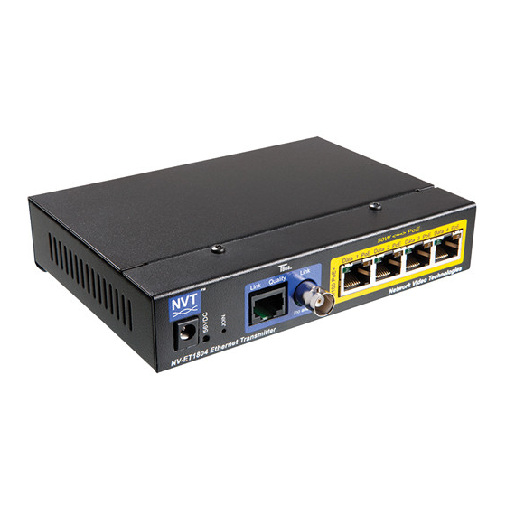
Four Port PoE+ Transmitter
®
Model NV-ET1804
IP Camera
PoE+
IP Camera
Cat5
IP Camera
≤328ft
(≤100m)
IP Camera
NV-ET1804
IMPORTANT SAFETY INSTRUCTIONS
1) Read these instructions.
2) Keep these instructions.
3) Heed all warnings.
4) Follow all instructions.
5) Do not use this apparatus near water.
6) Clean only with a dry cloth.
7) Install in accordance with the manufacturer's instructions.
8) Do not install near any heat sources such as radiators,
heat registers, stoves or other apparatus that produce heat.
9) Do not defeat the safety purpose of the polarized or
grounding-type plug. A polarized plug has two blades with
one wider than the other. A grounding type plug has two
blades and a third grounding prong. The wider blade or the
third prong are provided for your safety. If the provided plug
does not fit into your outlet, consult an electrician for
replacement of the obsolete outlet.
10) Protect the power cord from being walked on or pinched
particularly at plugs, convenience receptacles, and the point
where they exit from the apparatus.
11) Only use attachments/accessories specified by the
manufacturer.
12) Refer all servicing to qualified service personnel.
Servicing is required when the apparatus has been damaged
in any way, such as a power supply cord or plug is damaged,
liquid has been spilled, or objects have fallen into the appara-
tus, the apparatus has been exposed to rain or moisture,
does not operate normally, or has been dropped. This
installation should be made by a qualified service person and
should conform to all local codes.
13) Low Voltage Connections: The installation shall be in
accordance with the applicable provisions of the National
Electrical Code ANSI/NFPA 70, Article 800.90 and Canadian
Electrical Code Part 1, Section 60-504.
TO REDUCE THE RISK OF ELECTRICAL SHOCK, DO NOT
REMOVE COVER OR BACK. NO USER SERVICEABLE
PARTS INSIDE. REFER SERVICING TO QUALIFIED
SERVICE PERSONNEL.
WARNING: TO REDUCE THE RISK OF ELECTRICAL
SHOCK, DO NOT EXPOSE THIS APPARATUS TO RAIN OR
MOISTURE.
Page 1 of 2
any wire
Cat5
≤328ft
(≤100m)
NV-ET1801
or
56VDC
NV-ER1804
or
Power
NV-ER1808i
or
Supply
NV-ER1816i
!
This installation should be made by a qualified service
person and should conform to all local codes.
!
WARNING - Do not install the unit in an environment
where the operating ambient temperature exceeds 185° F
(85° C). The ventilation should not be impeded by covering
the unit with items, such as newspapers, table-cloths,
curtains, etc. No naked flame sources, such as lighted
candles should be placed on the apparatus.
!
WARNING
power supply outputs. Never use more than two power
supplies within a TBus channel. Never use more than
one 60 watt remote power supply on each TBus channel.
Do not connect additional loads which would exceed the
marked output current rating of the power supply.
!
WARNING - The apparatus shall not be exposed to
dripping or splashing and no objects filled with liquids, such
as vases, shall be placed on the apparatus.
!
WARNING - Use only a Certified power cord and plug
(coupler / mains) assemblies for location installed.
!
WARNING - Power cord is regarded as main
disconnect.
!
WARNING - The appliance coupler (power cord/
mains) shall remain readily operable.
!
WARNING - For safety, never put NVT signals in the
same conduit as high-voltage wiring.
This product is intended to be supplied by a certified power
source marked "Class 2" or "LPS" and rated 56 VDC, 30mA
minimum, 1,600mA maximum, which may or may not be
provided with the product.
Power supplies, when provided, are external inline, with an
IEC380-C14 power inlet and 6 ft (1.8 m) line-cord. Input
Voltage is 100 ~240 VAC 50-60 Hz. Output voltage is
56VDC, 1.07A or 1.6A. A molded P1J 5.5 mm barrel
connector provides a Class 2 (SELV) 56 VDC regulated
output. Line cord UL approved type SPT-2, SVT, or SJT, 18/3
AWG Min. 300VAC, 60° C Max. 15 ft (4.5 m) long. One end
with IEC380-C13 appliance coupler and the other end with
NEMA 1015P or equivalent for country.
Complies with these regulatory agency certifications and
directives.
UL Listed to IEC/UL 60950-1 Complies with FCC part 15A limits
Network Video Technologies
(+1) 650.462.8100 • +44 (0) 208 977-6614
nvt.com • www.nvt.com/email
Condensed Installation Guide
View the complete guide at www.nvt.com
Switch
Hybrid
Monitor
or
DVR
Router
or NVR
LAN / WAN
-
Do not interconnect multiple
FCC USER INFORMATION
This equipment has been tested and found to comply with
the limits for a Class A digital device, pursuant to part 15 of
the FCC Rules.
These limits are designed to provide
reasonable protection against harmful interference in a
residential installation. This equipment generates, uses, and
can radiate radio frequency energy and, if not installed and
used in accordance with the instructions, may cause harmful
interference to radio communications. However, there is no
guarantee that interference will not occur in a particular
installation. If this equipment does cause harmful interfer-
ence to radio or television reception, which can be
determined by turning the equipment off and on, the user is
encouraged to try to correct the interference by one or more
of the following measures:
- Reorient or relocate the receiving antenna.
- Increase the separation between the equipment and the
receiver.
- Connect the equipment into an outlet on a circuit different
from that to which the receiver is connected.
- Consult the dealer or an experienced radio/TV technician
for help.
WARNING
Changes or modifications not expressly approved by the
manufacturer could void the user's authority to operate the
equipment.
PRODUCT DESCRIPTION
The NVT Model NV-ET1804 Four-Port PoE+ Transmitter is a
compact media converter that allows 10/100 BaseT Ethernet
and PoE, PoE+, or high-power PoE to be transmitted using
coax, UTP, or other cable. These devices are typically used
in legacy installations where existing coax or other wire is
redeployed as part of an upgrade to IP. 56VDC class 2 power
at one transceiver is distributed to multiple remote transmit-
ters, and their PoE cameras (or other devices).
These transceivers are extremely simple to use, with no IP or
MAC address configuration required. Status LEDs indicate
power, link quality, and link connectivity/activity for RJ45
and BNC ports.
The NV-ET1804 is backed by NVT's award winning customer
support and limited lifetime warranty.
INSTALLATION INSTRUCTIONS
Before
installing,
NVT
downloading and reading the complete
installation manual from www.nvt.com.
Transceivers must be configured prior to use. See page 2.
Use one NV-ET1804 Transmitter at the remote (camera) end.
Multiple remote transceivers and cable runs may be
connected to the control room Receiver using any combina-
tion of star and daisy-chaining.
Data signals over the coax are capable of extended
distances, however voltage-drop in the 56V power distribu-
tion will often vary, depending on the camera's current draw
and wire resistance.
56VDC power is typically supplied to the whole system by the
control-room transceiver, however power may also be
provided locally if desired.
!
WARNING: For safety, never use more than
two power supplies within a TBus channel. Never use
more than one 60 watt remote power supply on each
TBus channel.
recommends
Advertisement

Subscribe to Our Youtube Channel
Related Manuals for NVT TBus NV-ET1804


Summary of Contents for NVT TBus NV-ET1804
- Page 1 BNC ports. particularly at plugs, convenience receptacles, and the point where they exit from the apparatus. WARNING - For safety, never put NVT signals in the The NV-ET1804 is backed by NVT’s award winning customer support and limited lifetime warranty.
- Page 2 ● ● Camera Position/Location NVT Transceiver Network Group Name ● ● Camera Make & Model Control Room NVT Transceiver MAC Address ● Camera MAC & IP Address ● Control Room Router Port Number ● Camera Login & Password This log may include essential documentation which will help you identify all system devices during and after deployment.
Need help?
Do you have a question about the TBus NV-ET1804 and is the answer not in the manual?
Questions and answers