Advertisement
Quick Links
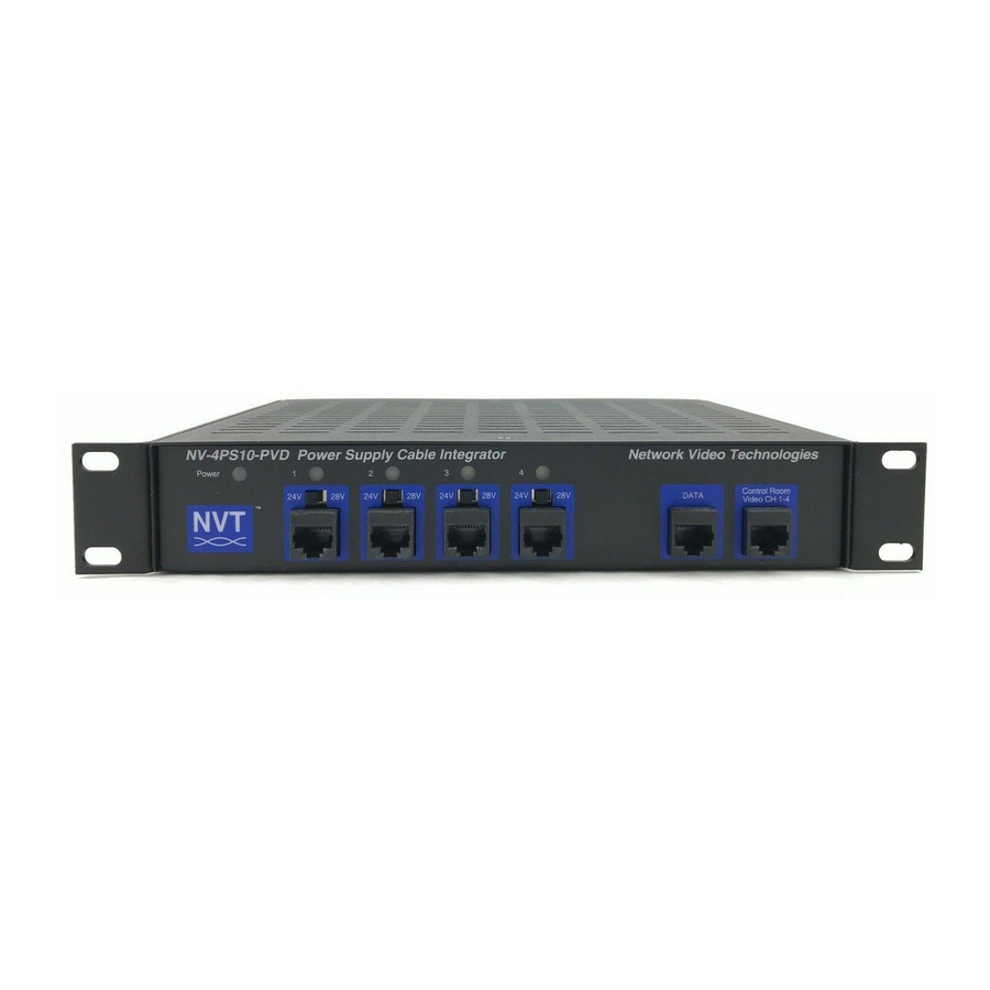
Power Supply Integrator Hub Installation Guide Models
NV-4PS10-PVD and NV-16PS10-PVD
Camera Location and
Transmitter Connections
Camera
NV-216A-PV
NV-218A-PVD
Camera
IMPORTANT SAFETY INSTRUCTIONS
1) Read these instructions.
2) Keep these instructions.
3) Heed all warnings.
4) Follow all instructions.
5) Do not use this apparatus near water.
6) Clean only with a dry cloth.
7) Do not block any ventilation openings.
8) Install in accordance with the manufacturer's instructions.
9) Do not install near any heat sources such as radiators, heat
registers, stoves or other apparatus (including DVRs) that
produce heat.
10) Do not defeat the safety purpose of the polarized or
grounding-type plug. A polarized plug has two blades with
one wider than the other. A grounding type plug has two
blades and a third grounding prong. The wider blade or the
third prong are provided for your safety. If the provided plug
does not fit into your outlet, consult an electrician for
replacement of the obsolete outlet.
11) Protect the power cord from being walked on or pinched
particularly at plugs, convenience receptacles, and the point
where they exit from the apparatus.
12) Only use attachments/accessories specified by the
manufacturer.
13) Use only with cart, stand, tripod, bracket, or table
specified by the manufacturer, or sold with the apparatus.
When a cart is used, use caution when moving the
cart/apparatus combination to avoid injury from tipover.
14) Unplug this apparatus during lightning storms or when
unused for long periods of time.
15) Refer all servicing to qualified service personnel.
Servicing is required when the apparatus has been damaged
in any way, such as a power supply cord or plug is damaged,
liquid has been spilled, or objects have fallen into the
apparatus, the apparatus has been exposed to rain or
moisture, does not operate normally,
or has been dropped.
TO REDUCE THE RISK OF ELECTRICAL SHOCK, DO NOT
REMOVE COVER OR BACK. NO USER SERVICEABLE
PARTS INSIDE. REFER SERVICING TO QUALIFIED
SERVICE PERSONNEL.
WARNING: TO REDUCE THE RISK OF ELECTRICAL
SHOCK, DO NOT EXPOSE THIS APPARATUS TO RAIN OR
MOISTURE.
This installation should be made by a qualified
service person and should conform to all local codes.
WARNING - Do not install the unit in an environment
where the operating ambient temperature exceeds 122° F
(50° C). The ventilation should not be impeded by
covering the ventilation openings with items, such as
newspapers, table-cloths, curtains, etc. No naked flame
sources, such as lighted candles should be placed on the
apparatus.
WARNING - Do not interconnect multiple
outputs.
WARNING - The apparatus shall not be exposed to
dripping or splashing and no objects filled with liquids,
such as vases, shall be placed on the apparatus.
WARNING - Use only a Certified power cord and plug
(coupler / mains) assemblies for location installed.
WARNING - Power cord is regarded as main
disconnect.
WARNING - The appliance coupler (power
cord/mains) shall remain readily operable.
WARNING - For safety, never put NVT signals in the
same conduit as high-voltage wiring.
WARNING - Do not restrict airflow around any active
powered NVT products.
IDF | Telecom Room
and Midspan Connections
Integrated PVD power with
New NV-4PS10-PVD or NV-16PS10-PVD
The NVT Power Supply Cable Integrator Hub combines a 1 Amp /channel
power supply with pass through video and telemetry data, for 4 to 16
cameras, all over UTP wire. Designed for installation in the wiring/IDF
telecom closet, or at the Control /MDF room, the Hub consolidates
connectivity via standard 4-pair RJ45 EIA/TIA 568B compliant premises
wiring and pinouts.
At the camera, Power, Video and Data connections are made using the
NV-216A-PV (power-video only), the NV-218A-PVD or the NV-226J-PV via an
RJ45 connector and a single 4-pair cable. Control/MDF room video
connections are achieved with a single 4-pair RJ45 cable for each group of
four cameras. Telemetry data connections (if required) also achieved with
another single 4-pair RJ45 cable for each group of four cameras.
The NV-4PS10-PVD supports up to four cameras in a compact wall- or
desk-mount chassis. The NV-16PS10-PVD supports up to 16 cameras in
a 1U wall- desk- or rack-mount chassis.
Wire Type
The Power Supply Cable Integrator Hub operates well with Category
Unshielded Twisted-Pair (UTP) wire, 24-22AWG (0,5-0,64mm)
The video signal may co-exist in the same wire bundle as other video,
telephone, data, control signals, or low-voltage power. It is also OK to run
NVT signals near electromagnetic fields (in accordance with National
Electrical Code, and other local safety requirements).
DO NOT USE individually shielded twisted pair. Overall shielded, multi-pair
(6pr +) is OK.
Do NOT use un-twisted wire.
Due to near-end crosstalk, do not send a transmit and a receive signal in the
same wire bundle. Exception: Up to 2,000ft (600m) Category 5. Wire in
underground conduit or wet locations must be polyethelyne-jacketed, gel-
filled. Wire in plenum environments must be plenum-rated, per local codes.
RS-422, RS-485, and Up-the-Coax Pan/Tilt/Zoom telemetry signals are
supported.
NVT recommends the use of factory-crimped RJ45 patch cables rather
than unreliable field-crimped RJ45s to connect between the NVT device
and an adjacent female RJ45 jack.
Wire Distance
All measured distances include any coax in the path.
Wire resistance may be measured with an ohm-meter by shorting the two
conductors together at the far end, and measuring the loop-resistance out
and back.
Loop Resistance per 1,000ft (300m)
24 AWG
(0,53 mm)
23 AWG
(0,57 mm)
22 AWG
(0,64 mm)
Wire distances are limited to the minimum of:
POWER DISTANCE - and -VIDEO DISTANCE
Video Distance
Wire distance between the camera through the Power Supply Cable
Integrator and on to the video receiver should not exceed:
Passive-to-Passive
750ft (225m)
Passive-to-Active
3,000ft (1km)
Cat 5 Wire Distance
780
700
630
550
475
400
315
235
Cat 5 Wire Distance
MDF | Control Room
and Receiver Connections
=
52 ohms
=
42 ohms
=
33 ohms
10 MHz
9 MHz
8 MHz
7 MHz
6 MHz
5 MHz
4 MHz
3 MHz
Active or Passive Receiver Hub
IP
Power Distance
Wire distance between the Power Supply Cable Integrator and the camera is
dependent on the camera's current draw. Please refer to the Power Distance
Guides below.
Fixed Camera 24VAC only, used with NV-216A-PV
Power Supply Voltage
24 VAC
21 VAC
Minimum Voltage at Camera
B&W Camera, 2.4 W
2-pair 24 AWG
789ft (240m)
2-pair 23 AWG
994ft (303m)
Color Camera, 4.8 W
2-pair 24 AWG
393ft (120m)
2-pair 23 AWG
495ft (151m)
Color Camera, 7.2 W
2-pair 24 AWG
262ft (80m)
2-pair 23 AWG
331ft (101m)
Fixed Dual Voltage 24VAC/12VDC Camera with NV-216A-PV
Power Supply Voltage
24 VAC
Minimum Voltage at Camera
14 VAC
B&W Camera, 2.4 W
2-pair 24 AWG
1,753ft (534m)
2-pair 23 AWG
2,210ft (674m)
Color Camera, 4.8 W
2-pair 24 AWG
874ft (266m)
2-pair 23 AWG
1,102ft (336m)
Color Camera, 7.2 W
2-pair 24 AWG
583ft (178m)
2-pair 23 AWG
735ft (224m)
P/T/Z 24VAC Camera used with NV-218A-PVD
Power Supply Voltage
24 VAC
Minimum Voltage at Camera
21 VAC
P/T/Z Camera, 21 W
2-pair 24 AWG
90ft (27m)
2-pair 23 AWG
113ft (35m)
Fixed 12VDC Camera used with NV-226J-PV
Power Supply Voltage
24 VAC
B&W Camera, 2.4 W
2-pair 24 AWG
1,586ft (748m)
2-pair 23 AWG
1,999ft (609m)
Color Camera 4.8 W
2-pair 24 AWG
795ft (242m)
2-pair 23 AWG
1,002ft (306m)
Connecting PVD at the Camera End
Use the NV-216A-PV for fixed cameras, the NV-218A-PVD for fixed or P/T/Z
cameras, or the NV-226J-PV for 12 VDC cameras. Install per the instructions
that come with the transmitting device using 4-pair wire and RJ45
connectors. Wiring pinouts are:
1
Wht/org
Video +
Video -
2
Org/wht
3
Wht/grn
Data +
Power -
Blu/wht
4
5
Wht/blu
Power +
Data -
6
Grn/wht
7
Wht/brn
Power +
Power -
8
Brn/wht
Connecting PVD at the Power
Supply Cable Integrator Hub
Bring the 4-pair PVD cable from each camera back to the location of the
Power Supply Cable Integrator. NVT recommends that an RJ45 Patch Panel
be used here in conjunction with RJ45 patch-cords. Use of these EIA/TIA
568B compliant practices allows for easy testing with an RJ45 (LAN) tester,
as well as moves and changes.
Connect the PVD signals into ports on the front of the Power Supply Cable
Integrator.
28 VAC
21 VAC
1,840ft (561m)
2,320ft (707m)
916ft (279m)
1,155ft (352m)
612ft (186m)
771ft (235m)
28 VAC
14 VAC
2,454ft (748m)
3,094ft (943m)
1,223ft (373m)
1,542ft (470m)
816ft (249m)
1,029ft (314m)
28 VAC
21 VAC
210ft (64m)
265ft (81m)
28 VAC
2,220ft (677m)
2,799ft (853m)
1,113ft (339m)
1,403ft (428m)
Advertisement

Related Manuals for NVT NV-4PS10-PVD


Summary of Contents for NVT NV-4PS10-PVD
-
Page 1: Important Safety Instructions
4-pair RJ45 cable for each group of four cameras. registers, stoves or other apparatus (including DVRs) that Color Camera, 4.8 W produce heat. The NV-4PS10-PVD supports up to four cameras in a compact wall- or 2-pair 24 AWG 393ft (120m) 916ft (279m) 10) Do not defeat the safety purpose of the polarized or desk-mount chassis. -
Page 2: Connecting Power
NVT, any warranty for those A spare fuse is located inside the fuse holder. products will cease and NVT will have no further liability as it pertains to those products. Mechanical (Excluding brackets and connectors)
Need help?
Do you have a question about the NV-4PS10-PVD and is the answer not in the manual?
Questions and answers