
Subscribe to Our Youtube Channel
Related Manuals for Equilibar EPR Series


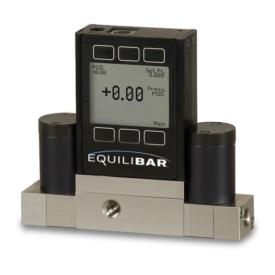
Summary of Contents for Equilibar EPR Series
- Page 1 Installation and Operating Manual EPR Series Electronic Pressure Regulator MANUAL FOR NON-ATEX, NON-CSA, NON-HAZARDOUS AREA MODELS...
- Page 2 Make sure that you have read and understand these directions before using, installing, or maintaining an EPR Series Electronic Pressure Regulator for non-ATEX Use. Take steps to ensure this instruction manual reaches the operator of this regulator and stays with the regulator throughout its lifetime.
-
Page 3: System Installation And Hazard Analysis
Be sure to include the full part explode. number and serial number of the EPR you are inquiring about. (01-828-650-6590, info@ The Equilibar EPR is not a “Safety Accessory” as • equilibar.com) defined by the Pressure Equipment Directive 2014/68/EU. Be sure to install appropriate Take precautions to prevent injury to personnel •... -
Page 4: Table Of Contents
PID TUNING RS-232 / RS-485 COMMUNICATIONS SETUP CHANGING FROM STREAMING TO POLLING MODE COLLECTING DATA & DATA FORMAT SENDING A SIMPLE SCRIPT FILE TO HYPERTERMINAL® LIST OF SUPPORTED UNITS OF MEASURE TROUBLESHOOTING MAINTENANCE AND RECALIBRATION www.equilibar.com Page 4 of 24 828.650.6590... -
Page 5: Introduction
EPR’s electronic control circuit. The control circuit compares the internal sensor feedback signal to the command signal input. Any difference between the two signals Fig. 1 EPR pilot operating an Equilibar H3P back pressure regulator www.equilibar.com Page 5 of 24 11/3/20 R2... -
Page 6: Plumbing
Do not remove allow the controller to be used over its full scale this filter. range. factory-installed filter inlet port exhaust port process port Fig. 2 Typical EPR Plumbing Diagram www.equilibar.com Page 6 of 24 828.650.6590... -
Page 7: Power And Signal Connections
A 2.1mm, positive center, 12-30 Vdc AC/DC adapter rated for at least 250 mA is required to use the adapter jack in a EPR Series controller. NOTE: 4-20mA analog output requires at least 15 Vdc. -
Page 8: Input Signals Analog
A remote tare can be achieved by momentarily grounding pin 4 to tare. Controllers: A simple method for providing setpoint to controllers www.equilibar.com Page 8 of 24 828.650.6590... -
Page 9: Rs-232 / Rs-485 Digital Input Signal
8 Pin Mini-DIN Connector 9 PIN SERIAL CONNECTION 8 PIN MINI-DIN CONNECTION Function Function DC Common (Ground) DC Common (Ground) Transmit Receive Receive Transmit DB9 to Mini-DIN Connection for RS-232 / RS-485 Signals www.equilibar.com Page 9 of 24 11/3/20 R2... -
Page 10: Standard Db9 Input Signal
Do not connect RS-485 to RS-232 units or cables. Damage will occur! Check part number or contact factory to verify RS-485 functionality. Due to variance in cable manufacturing, please identify proper wiring/ pins via continuity check & color when using blunt cut multi-strand cables. www.equilibar.com Page 10 of 24 828.650.6590... -
Page 11: Output Signals
Input Signal (Pin 3), and Ground (Pin 8) to your computer serial port as shown on page 9. (See page 17 for details on accessing RS-232 / RS-485 output.) Purple (DC common Ground) Optional Multiple Device (Addressable) Wiring Configuration for RS-485 www.equilibar.com Page 11 of 24 11/3/20 R2... -
Page 12: Getting Started - Display Screen And Menus
When any item flashes, the pressure measurement is not accurate. Reducing the pressure to within specified limits will return the unit to normal operation and accuracy. If the unit does not return to normal operation, contact Equilibar. www.equilibar.com Page 12 of 24... - Page 13 MENU STRUCTURE The tree diagram below outlines the menu structure for the EPR Series controllers. To access a specific menu, follow the appropriate tree, by pressing the button(s) listed until you reach the desired menu screen. Detailed menu operations can be found on pages 14-15.
-
Page 14: Control Menu & Submenu Details
The controller must be left in the default AUTO when removed from the line and open, it is a good TARE OFF mode except when actually taring the indication that it was given a false zero. controller as explained below. www.equilibar.com Page 14 of 24 828.650.6590... - Page 15 CAUTION! Never leave a Controller with a non-zero setpoint if no pressure is available to make flow. The controller will apply full power to the valve in an attempt to reach the set-point. When there is no flow, this can make the valve very HOT! www.equilibar.com Page 15 of 24 11/3/20 R2...
-
Page 16: Pid Tuning
PID TUNING EPR Series controllers allow you to adjust the process cycle to process cycle, thus performing Proportional, Integral and Differential terms of the integration function automatically. the PID control loop. Increasing the ‘P’ gain will promote the tendency To change the PID loop parameters, push the of the system to overshoot, ring, or oscillate. -
Page 17: Rs-232 / Rs-485 Communications Setup
To read register 91, type “*r91” followed by “Enter”. To modify register 91, type “*w91=X”, where X is a positive integer from 1 to 65535, followed by “Enter”. To return to the recommended factory default streaming speed, type “*w91= 50”. www.equilibar.com Page 17 of 24 11/3/20 R2... -
Page 18: Changing From Streaming To Polling Mode
Instead, each should be individually attached to the RS-232 / RS- 485 line, given an address, and taken off. After each unit has been given a unique address, they can all be put back on the same line and polled individually. www.equilibar.com Page 18 of 24 828.650.6590... - Page 19 Transfer Menu. Type in the path and file name you wish to use. Push the start button. For EPR Series Controllers, there are 2 columns When the data collection period is complete, of data representing pressure and setpoint.
-
Page 20: Sending A Simple Script File To Hyperterminal
Click O.K. You have now created a “script” file to send to HyperTerminal. Close the file and exit the text www.equilibar.com Page 20 of 24 828.650.6590... - Page 21 0 – 64000 percent of full scale VALVE DRIVE UNITS Label Notes count +/- 65536 at full drive Percent of full scale drive www.equilibar.com Page 21 of 24 11/3/20 R2...
-
Page 22: Troubleshooting
After installation, there is no pressure. EPR Series Controllers incorporate normally closed valves and require a setpoint to operate. Check that your setpoint signal is present and supplied to the correct pin and that the correct input is selected under the SETPT SOURCE list in the control set up display (page 14). -
Page 23: Maintenance And Recalibration
CLEANING EPR Series Pressure Controllers require no periodic cleaning. If necessary, the outside of the controller can be cleaned with a soft dry cloth. Avoid excess moisture or solvents. For repair, recalibration or recycling of this product, please contact Equilibar Tel: +1 (828) 650-6590 inquiry@equilibar.com... - Page 24 320 Rutledge Rd. • Fletcher, NC 28732 USA • Tel: +1 (828)650-6590 • www.equilibar.com • inquiry@equilibar.com Made in the Equilibar’s quality system is ISO 9001:2015 certified. ©2020 Equilibar, LLC...
Need help?
Do you have a question about the EPR Series and is the answer not in the manual?
Questions and answers