Table of Contents
Advertisement
Advertisement
Table of Contents

Related Manuals for Zenbooth Solo

Summary of Contents for Zenbooth Solo
- Page 1 Zenbooth Solo Build Instructions...
- Page 3 / / TABLE OF CONTENTS Content Page Introduction Product Specs Tools - Included Tools - Needed Hardware List Small Parts Wall Panels Large Parts Assembly Instructions 11-34 Product Quality, Damage & Warranty Tips Trouble Shooting Notes...
- Page 4 / / INTRODUCTION Dear valued customer, Thank you! The entire Zenbooth team would like to congratulate you on your new Zenbooth Solo. We promise you will not be disappointed with your purchase! Founded in 2016, Zenbooth designs and manufactures all of its products in Berkeley, California. We are committed to offering the highest quality possible, while constantly reducing our environmental impact to a minimum.
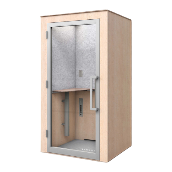
- Page 5 / / PRODUCT SPECS Specifications - Free-standing, modular privacy booth. Measurements Door Exterior Size: 36” wide self-closing door. 84.5”x45.5”x41” (HxWxD) 18.8” door handle. Interior Size: 83”x36.75”x33.25” (HxWxD) Weight Desk 500 lbs Surface height fixed desk: 41” Surface height range of adjustable desk: 29”-55” Surface dims: 30”x16.75”...
- Page 6 / / PARTS OVERVIEW TOOLS INCLUDED Hex Key 3mm Point Size Point Size Point Size Hex Key 4mm Shims 4x (Door Handle #2 Phillips #3 Phillips #2 Square (Spring Hinge) assembly) Drive Bit Drive Bit Drive Bit / / PARTS OVERVIEW TOOLS NEEDED Drill Ladder...
- Page 7 / / PARTS OVERVIEW HARDWARE 7 x 1/2” Phillips Drive Screws 26 x 2” Square Drive Screws 13 x 1 1/2” Phillips Drive Screws (Desktop Column to Wall) (Walls/Floor/Door Jam) (Door Hinge - Booth Side) 5 x 3/4” Hex Drive Screws 13 x 1/2”...
- Page 8 / / PARTS OVERVIEW SMALL PART BOX Door Frame Header Cap Vent Ducts Door Frame Header Outside/ Inside Door Handle Electric Lift Desktop...
- Page 9 / / PARTS OVERVIEW WALL PANELS Exterior Right Wall Exterior Left Wall Interior Left Wall Interior Right Wall *Exterior Rear Wall + Facade ship together *Insulation *Acoustic Paneling Interior Rear Wall Exterior Rear Wall Facade...
- Page 10 / / PARTS OVERVIEW LARGE PART BOX Skylight Ceiling Anti Fatigue Mat Floor Door...
- Page 11 / / ASSEMBLY NOTES Before assembly! Before beginning assembly, we recommend consulting a professional insured Zenbooth installer or general contractor. Warranty may be void if components are improperly installed. Contact us at : support@zenbooth.net for any additional information or customer support.
- Page 12 / / ASSEMBLY NOTES Rear Step 01 Base Place Base on level ground. Front Note: Make sure the Base ground is level and flat. Step 02 Left Wall Check alignment! Insert The Make sure the Interior Left joining grooves Wall into the are aligned.
- Page 13 / / ASSEMBLY NOTES Step 03 Interior Rear Slide the Interior Rear Be sure the top of Wall into the joining all Walls are flush grooves of the Base throughout your and Left Wall. build once the Walls are set. Interior Rear Wall The bottom of the Walls should sit inside the grooves...
- Page 14 / / ASSEMBLY NOTES Step 04 Right Wall Pilot Hole Insert the Interior Right Wall into the Base and Interior Rear Wall. Using 2” square drive screws, fasten the Right Interior Walls to the Rear Wall. Interior Right Wall Pilot Hole 6 x 2”...
- Page 15 / / ASSEMBLY NOTES Step 05 Duct: Vent Ducts Make sure the power and fan Slide the Top cord are held in & Bottom Vent place through Ducts into the notch. slots on the Inside of the Side Walls, bottoming it out against the Rear Wall.
- Page 16 / / ASSEMBLY NOTES Step 07 Retrieve Power Cord Make sure you pull the Power Cord through the opening in the Exterior Rear Wall. Electrical Outlet Step 08 Fasten Rear Wall Using 2” square drive screws, fasten Pilot the Rear Wall. Hole Light Cord 4 x 2”...
- Page 17 / / ASSEMBLY NOTES Step 09 Connect Fan Cord Make sure the 2-Pin Fan connectors are connected. Power Supply Step 10 Hatch Plate Once all cords have been connected and cleared, insert the Hatch Plate and move the Grommet in place.
- Page 18 / / ASSEMBLY NOTES Step 11 Insert Exterior Wall Insert the Exterior Left and Right Walls to the Base and Exterior Rear Wall. One top corner of each panel is labeled L or R. Exterior Left Wall Applying pressure at bottom edge of Exterior Right Wall a Wall works well for pushing it into...
- Page 19 / / ASSEMBLY NOTES Step 12 Insert Door Header Evenly insert the Door Header into the Make sure all Walls corresponding and Header are notches in the fully inserted and left and right. flush together! Door Frame Header Step 13 Cap the Header Complete the Door Frame by...
- Page 20 / / ASSEMBLY NOTES Step 14 Install the Facade Inserting the Facade into the Base at an angle will help ensure the correct fit. The outer edge of the Facade should bottom out on top of the Floor. Facade Step 15 Fasten The Facade Pilot Pilot...
- Page 21 / / ASSEMBLY NOTES Step 16 Pilot Hole Fasten the Ceiling Guide the Ceiling into place by starting from one corner and working it down onto the top of the booth until it is seated. Next, while standing on a step ladder, locate the eight pre-drilled holes on the top and...
- Page 22 / / ASSEMBLY NOTES Pilot Hole Step 17 Fasten the Skylight Remove protective film from the Skylight. Using a step ladder, position the Skylight on the Skylight top of the booth. Align the Skylight with the corner marks as to not obstruct the ventilation.
- Page 23 / / ASSEMBLY NOTES Step 18 Fasten The Walls Screw 2” square drive screws through the pre-drilled pilot holes at the bottom of the Interior Walls to attach the booth to the Base. Pilot Hole (Right Side) 6 x 2” Square Drive Screws Pilot Hole...
- Page 24 / / ASSEMBLY NOTES Step 19 Attach Hinges to Door Hinge Plate (Top) Use 1/2” Philips screws to attach Top and Bottom Hinges to Door. Hinge Plate (Bottom) 8 x 1 1/2” Phillips Drive Screws...
- Page 25 / / ASSEMBLY NOTES Step 20 Install Door Handle Attach Outside Door Handle: Screw the Door Inside Door Handle Handle to the provided bolts through the Door Frame. Attach Inside Door Handle: Use the provided 3mm hex key to tighten the small hex bolts in the Handle to secure it.
- Page 26 / / ASSEMBLY NOTES Step 21 Fasten Hinges Using the point Hinge Plate (Top) size 3 Philips Spring Hinge Driver bit and (Middle) screws, attach the two Hinge Plates (Top & Bottom) to the Door Frame of the booth. Make sure the Hinges are fully inserted into the pockets in the...
- Page 27 / / ASSEMBLY NOTES Step 22 Land Door on Hinges Hinge Plate Hang the Door (Top + Bottom) on the mounted Hinges. With the Door hung in place, connect the positioned Spring Hinge (Middle) to the door. It may be necessary to open the Door 180 degrees to mount this Hinge.
- Page 28 / / ASSEMBLY NOTES Step 23 Set Spring Hinge Place Door in closed position. Insert Hex Wrench in Hex Hole. Rotate Hex Wrench clock- wise (while viewing from the adjustment end of hinge) to increase tension and insert locking pin loosely in adjusting hole.
- Page 29 / / ASSEMBLY NOTES Step 24 Install Electric Lift Column Fasten Desktop to Electric Lift Column, using the Point Size 2 Phillips Driver bit and 1/2” Silver Panhead screws. Electric Lift Desktop Pilot Hole 2 x Each Side 4 x 1/2” Panhead Screws (Brackets to Desk)
- Page 30 / / ASSEMBLY NOTES Step 25 Install Desk Brackets Using the Point Size 2 6 x 3/4” Panhead Screws (Brackets to Desk) Phillips Driver bit and six 3/4” Black Panhead screws, align the brackets with the pilots and mount them to the Pilot Hole Wall.
- Page 31 / / ASSEMBLY NOTES Step 26 Place Anti-Fatigue The Mat should fit squarely between all three Interior Walls and tuck under the Rear Wall Vent. Anti Fatigue Mat Step 27 Relocate Booth After completing the build, move booth into its final position.
- Page 32 / / ASSEMBLY NOTES Step 28 Door Tuning After the booth is fully assembled and is in Door Drop its final location, check the Door for proper If the Door drops in height alignment along the top from left to right (this is the right edge.
- Page 33 / / ASSEMBLY NOTES Step 29 Shim Locations Insert a Shim in the back right corner for Door drop and back left corner for Door rise. If the Door drops, place If the Door rises, place shim at marked areas to shim at marked areas to correct.
- Page 34 / / ASSEMBLY NOTES Step 30 Door Sweep Lower the Door Sweep into position to close the air- gap at the bottom of the Door. Then open and close the Door to ensure the lowered Door does not impede the closure of the Door.
- Page 35 Zenbooth products are sold with a limited warranty against defects in materials and workmanship for a period of three years from the delivery date. Zenbooth reserves the right to repair or replace defective merchandise at its sole discretion. This limited warranty does not extend to other materials supplied by the purchaser or damage caused by shipping, accident, abuse, misuse, cleaning, or normal wear and tear.
- Page 36 Not sure how many booths you need for your team? We typically recommend at least 1 Zenbooth Solo for every 5-10 employees in your office, and at least one of our larger models for every 15 employees in your office. At Zenbooth HQ, we have about 1 booth per person, and they’re always full!
- Page 37 Repeat step 23 again, tightening the spring another notch. Q: My fan/light stays on continually. If the timer does not seem to be turning the product off after 10 minutes, please contact Zenbooth support. Q: My booth is stuffy or warm.
- Page 38 / / NOTES...
- Page 40 Zenbooth Inc. 650 University Ave Suite #10 Berkeley, CA 94710 Copyright © 2020. All Rights Reserved...
Need help?
Do you have a question about the Solo and is the answer not in the manual?
Questions and answers