
Related Manuals for ProLights CYBER384


Summary of Contents for ProLights CYBER384
- Page 1 CYBER384 DMX CONTROLLER Manuale Utente User Manual Mixer Per teste Mobili motorizzati...
- Page 2 Music & Lights S.r.l. si riserva ogni diritto di elaborazione in qualsiasi forma delle presenti istruzioni per l’uso. La riproduzione - anche parziale - per propri scopi commerciali è vietata. Al fine di migliorare la qualità dei prodotti, la Music&Lights S.r.l. si riserva la facoltà di modificare, in qualunque momento e senza preavviso, le specifiche menzionate nel presente manuale di istruzioni.
-
Page 3: Table Of Contents
4. 3 Creazione di un chase 4. 4 Inserimento di una scena in un chase 4. 5 Eliminare di una scena in un chase 4. 6 Copiare un banco in un chase Contenuto dell'imballo: • CYBER384 • Alimentatore 12V DC 500mA • Manuale utente... -
Page 4: Avvertenze Generali
CYBER 384 ATTENZIONE! Prima di effettuare qualsiasi operazione con l’unità, leggere con attenzione questo manuale e conservarlo accuratamente per riferimenti futuri. Contiene informazioni importanti riguardo l’installazione, l’uso e la manutenzione dell’unità. SICUREZZA Avvertenze generali • I prodotti a cui questo manuale si riferisce sono conformi alle Direttive della Comunità Europea e per- tanto recano la sigla . -
Page 5: Informazioni Generali
CYBER 384 INFORMAZIONI GENERALI Spedizioni e reclami Le merci sono vendute “franco nostra sede” e viaggiano sempre a rischio e pericolo del distributore/clien- te. Eventuali avarie e danni dovranno essere contestati al vettore. Ogni reclamo per imballi manomessi dovrà essere inoltrato entro 8 giorni dal ricevimento della merce. Garanzie e resi Il prodotto è... -
Page 6: Introduzione
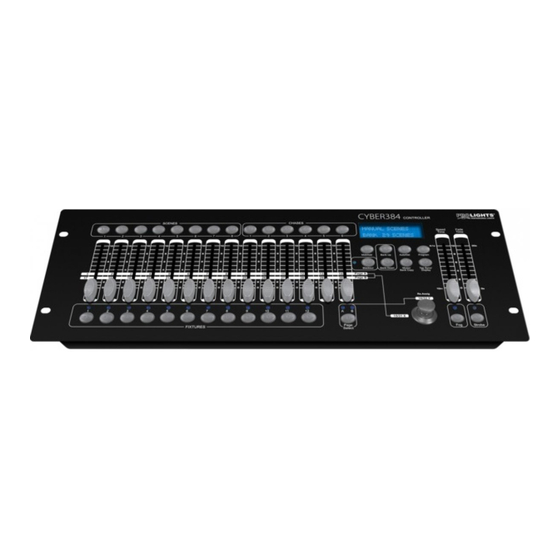
CYBER384 è munito di 14 faders e Joystick assegnabile per controllare fino a 12 proiettori con 32 canali DMX. La memoria interna permette di personalizzare 30 banchi di 8 programmi ciascuno, per un massimo di 240 scene. -
Page 7: Elementi Di Comando E Di Collegamento
CYBER 384 1.3 ELEMENTI DI COMANDO E DI COLLEGAMENTO MIDI STROBE DMX OUT OUTPUT Power In polarity select 12V DC 500mA Pannello posteriore 10 11 12 14 15 Fig.1 Pannello frontale 1. MIDI IN; riceve i dati MIDI 11. Tasto BLACKOUT 2. -
Page 8: Installazione/Connessioni
CYBER 384 - 2 - INSTALLAZIONE / CONNESSIONI 2.1 INSTALLAZIONE Il CYBER 384 può essere installato su una superficie piana. Si prega di far riferimento al disegno del pan- nello inferiore dell’unità, riportato di seguito (fig.2). Esso espone in dettaglio le dimensioni utili per il mon- taggio. -
Page 9: Costruzione Del Terminatore Dmx
CYBER 384 ATTENZIONE La parte schermata del cavo (calza) non deve mai essere collegata alla terra dell’impianto; ciò comporte- rebbe malfunzionamenti delle unità e dei controller. Per passaggi lunghi può essere necessario l’inserimento di un amplificatore DMX. In tal caso, è sconsigliato utilizzare nei collegamenti cavo bilanciato microfonico poiché non è in grado di trasmettere in modo affidabile i dati di controllo DMX. -
Page 10: Indirizzamento Dmx
CYBER 384 2.4 INDIRIZZAMENTO DMX CYBER384 permette di gestire fino ad 12 proiettori con funzionamento ad 16/32 canali ciascuno. L’assegnazione dell’indirizzo di start delle unità deve essere eseguita secondo la seguente tabella. L’inter- vallo tra le unità è costituito da 32 canali. -
Page 11: Funzioni E Impostazioni
3.2 ASSEGNAZIONE DEI CURSORI Il CYBER384 dispone di una funzione che consente di unificare o combinare le caratteristiche di controllo di diversi dispositivi. In questo modo è possibile ri-assegnare le diverse funzioni ai cursori affinché si pos- sano gestire, su tutti i dispositivi, le stesse funzioni (ad esempio: canali colori, canali gobo, dimmer ecc.). -
Page 12: Inversione Cursori
CYBER 384 3. Mentre si tiene premuto il tasto [FIXTURES] definito in precedenza, premere il tasto [FIXTURES], da i 1 a 12 relativo al dispositivo dove copiare l’assegnazione dei cursori. 4. Mentre si premono i tasti [FIXTURES], premere anche il tasto [MIDI/ADD] 5. -
Page 13: Programmazione
- 4 - PROGRAMMAZIONE Un programma (banco) è una sequenza (chases) di diverse scene (passi) richiamate l’una dopo l’altra. Con il CYBER384 è possibile realizzare fino a 6 set di programmi ciascuno per un max di 240 scene. 4.1 MODALITA PROGRAM Per abilitare la modalità... -
Page 14: Inserimento Di Una Scena In Un Chase
CYBER 384 4.4 INSERIMENTO DI UNA SCENA IN UN CHASE 1. Tenere premuto per circa 3 secondi il tasto [PROGRAM] per entrare nella modalità. 2. Premere il tasto [CHASES] 1 - 6 desiderato. 3. Utilizzare i tasti [BANK UP]/ [BANK DOWN] per selezionare il punto dove inserire la scena. 4. -
Page 15: Modifica Della Programmazione
CYBER 384 - 5 - MODIFICA DELLA PROGRAMMAZIONE 5.1 ELIMINARE UNA SCENA 1. Entrare nella modalità PROGRAM. 2. Selezionare il banco attraverso i tasti [BANK UP]/ [BANK DOWN] che contiene la scena da eliminare. 3. Tenere premuto il tasto [AUTO/DEL] mentre si preme il tasto [SCENES] 1 - 8 relativo alla scena che si desidera eliminare. -
Page 16: Playback
CYBER 384 - 6 - PLAYBACK Il CYBER384 dispone di tre modalità di esecuzione per le scene ed i chase: • modalità manuale • modalità musicale • modalità automatica ESECUZIONE SCENE 6.1 MODALITÀ MANUALE Questa modalità verrà attivata quando si accende il controller. -
Page 17: Esecuzione Chase In Modalità Musicale
CYBER 384 ESECUZIONE CHASE 6.4 MODALITÀ MANUALE 1. Entrare nella modalità. 2. Premere il tasto [CHASES] 1 - 6 relativo al chase che si vuole eseguire. 3. Premere il tasto [TAPS SYNC/DISPLAY] 4. Usare i tasti [BANK UP] e [BANK DOWN] per muoversi attraverso il chase. 6.5 MODALITÀ... -
Page 18: Midi
CYBER 384 - 7 - MIDI 7.1 FUNZIONAMENTO MIDI 1. Premere il tasto [MIDI/ADD], il LED del display lampeggerà mostrando il canale Midi. 2. Premere i tasti [BANK UP] / [BANK DOWN] per selezionare i canali DMX 01-16 da assegnare al canale Midi. -
Page 19: Funzione Tap Sync
7.3 CONTROLLO MACCHINA DEL FUMO Il controller CYBER384, dispone di un controllo dedicato per attivare o disattivare la macchina del fumo. É possibile collegare la macchina del fumo servendosi del collegamento a 5 pin posto sul pannello poste- riore del controller. -
Page 20: Manutenzione
CYBER 384 - 8 - MANUTENZIONE 8.1 RISOLUZIONE DEI PROBLEMI GENERALE Problemi Possibili cause Possibili rimedi Mancanza di alimentazione di rete Verificare la presenza di alimentazione di rete • • Il dispositivo non è alimentato Cavo di alimentazione danneggiato Controllare il cavo di alimentazione •... - Page 22 All rights reserved by Music & Lights S.r.l. No part of this instruction manual may be reproduced in any form or by any means for any commercial use. In order to improve the quality of products, Music&Lights S.r.l. reserves the right to modify the characteristics stated in this instruction manual at any time and without prior notice.
- Page 23 4. 3 Create a chase 4. 4 Adding a step to a chase 4. 5 Delete a scene/step in a chase 4. 6 Copy a bank into a chase Packing content: • CYBER384 • External 12V DC 500mA adapter • User manual...
-
Page 24: General Instructions
CYBER 384 WARNING! Before carrying out any operations with the unit, carefully read this instruction manual and keep it with cure for future reference. It contains important information about the installation, usage and maintenance of the unit. SAFETY General instruction • The products referred to in this manual conform to the European Community Directives and are there- fore marked with . -
Page 25: General Information
CYBER 384 GENERAL INFORMATION Shipments and claims The goods are sold “ex works” and always travel at the risk and danger of the distributor. Eventual dam- age will have to be claimed to the freight forwarder. Any claim for broken packs will have to be forwarded within 8 days from the reception of the goods. -
Page 26: Introduction
CYBER384 is built with 14 reversible faders and assignable joystick to control up to 12 fixtures with 32ch each. The internal memory has 30 baks of 8 scenes, 240 scenes max. -
Page 27: Operating Elements And Connections
CYBER 384 1.3 OPERATING ELEMENTS AND CONNECTIONS MIDI STROBE DMX OUT OUTPUT Power In polarity select 12V DC 500mA Rear panel 10 11 12 14 15 Fig.1 Front panel 1. MIDI IN; reiceives MIDI data through bank in ascending or descending order 2. -
Page 28: Installation/ Connections
- 2 - INSTALLATION / CONNECTIONS 2.1 INSTALLATION Install the CYBER384 on a plane surface. Please see the drawing below (fig.2), which shows the back of the controller. It details the dimensions for mounting. This will aid in placing the holes for installation. -
Page 29: Construction Of The Dmx Termination
CYBER 384 ATTENTION The screened parts of the cable (sleeve) must never be connected to the system’s earth, as this would cause faulty fixture and controller operation. Over long runs can be necessary to insert a DMX level matching amplifier. For those connections the use of balanced microphone cable is not recommended because it cannot transmit control DMX data reliably. -
Page 30: Addressing
CYBER 384 2.4 ADDRESSING The CYBER384 allows you to program 12 scanners with 16/32 DMX channels each. You have to address every projector to the respective starting address. Please note that the DMX operator assigns the DMX starting addressed every 32 steps (see chart). -
Page 31: Functions And Settings
CYBER 384 - 3 - FUNCTIONS AND SETTINGS 3.1 BASIC This fixture requires an external power supply. Before powering on the unit, make sure the power supply voltage to which you are connecting it is correct. Connect the connection cable of the power unit with the DC in socket. -
Page 32: Copying Physical Fader Assignment
CYBER 384 3.4 COPYING PHYSICAL FADER ASSIGNMENT This process will copy the physical fader assignment from one fixture into another fixture. 1. Press [PROGRAM] and [TAP SYNC/DISPLAY]. This will enter the physical fader assignment mode. 2. Press & hold the fixture button that contains the desired physical fader assignment. 3. -
Page 33: Programming
- 4 - PROGRAMMING ENTERING PROGRAM MODE No programming may be done on the CYBER384 without first entering program mode. You will find refer- ences to this process in many other sections of this user manual. Please see the steps below to enter this mode. -
Page 34: Adding A Step To A Chase
CYBER 384 9. Continue through steps 6~8 until all of the scenes have been added to the chase. 10. Exit program mode. NOTE - Remember the scene number on the controller that you will edit, otherwise, you could overwrite the contents of another scene. Deselect Blackout if LED is lit. -
Page 35: Programming Modifications
CYBER 384 - 5 - PROGRAMMING MODIFICATIONS 5.1 DELETE ONE SCENE Use this function to delete one of the scenes in the controller. Repeat this process for each scene that you need to delete. 1. Enter program mode. 2. Locate the scene in the program BANK. Use [BANK UP/DOWN] to navigate program banks. 3. -
Page 36: Playback
CYBER 384 - 6 - PLAYBACK SCENE PLAYBACK 6.1 MANUAL SCENE PLAYBACK (SINGLE) 1. This controller is capable of playing back a single scene at a time. The [SPEED] and [FADE TIME] faders will not function in this mode. Please see the instructions below for further explanation. 2. -
Page 37: Auto Chase Playback
CYBER 384 6.5 AUTO CHASE PLAYBACK You may control the playback of the chases in this controller by using the [SPEED] and [FADE TIME] faders. Please see the instructions below for further explanation. 1. Activate the desired chase by pressing [CHASE 1~6]. 2. -
Page 38: Midi
CYBER 384 - 7 - MIDI The controller will only respond to MIDI commands on the MIDI channel when it is set to full stop. Perform all MIDI control using Note on commands. All other MIDI instructions are ignored. To stop a chase, send the blackout on note. -
Page 39: Tap Sync
(bpm). This will allow the lights to synchronize with the music. 7.3 FOG CONTROL The CYBER384 has a dedicated fog button that will work with compatible fog machines. This button works with the dedicated 5-pin connector that is located on the back panel of the controller. -
Page 40: Maintenance
CYBER 384 - 8 - MAINTENANCE 8.1 GENERAL TROUBLESHOOTING Problems Possible causes Checks and remedies No power Check for power on mains • • Device does not power up Loose power cord Check power cord • • Wrong DMX addressing Check control panel and unit addressing •... - Page 43 Place Stamp Here Affrancare Spett.le Music&Lights S.r.l. Via Appia Km 136.200 04020 Itri (LT) Italy "...
- Page 48 Music & Lights S.r.l. entertainment technologies Via Appia km 136,200 - 04020 Itri (LT) ITALY ISO 9001:2008 tel. +39 0771 72190 fax +39 0771 721955 Certified Company www.musiclights.it info@musiclights.it...
Need help?
Do you have a question about the CYBER384 and is the answer not in the manual?
Questions and answers