Table of Contents
Advertisement
Quick Links
A A V I X
O U T D O O R S
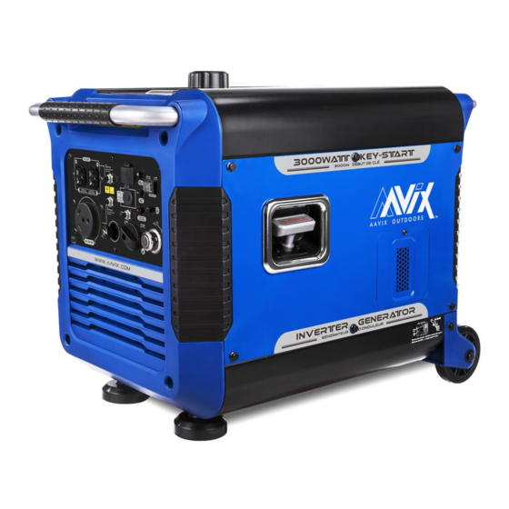
3000W DIGITAL INVERTER GENERATOR
FOR SERVICE CALL: (USA)1-866-591-8921/(CANADA)1-514-885-0916
WARNING : To reduce the risk of injury, user must read this manual before assembling, operating
and maintaining this unit, You are responsible for operating the product properly & safely.
Version: V1.20171124
Advertisement
Table of Contents

Related Manuals for AAVIX A112004

Summary of Contents for AAVIX A112004
- Page 1 A A V I X O U T D O O R S 3000W DIGITAL INVERTER GENERATOR FOR SERVICE CALL: (USA)1-866-591-8921/(CANADA)1-514-885-0916 WARNING : To reduce the risk of injury, user must read this manual before assembling, operating and maintaining this unit, You are responsible for operating the product properly & safely. Version: V1.20171124...
-
Page 2: Table Of Contents
Subsequent starting of the generator………………………………………………………19 Using the generator…………………………………………………………………………….…..21 Maintenance……………….…………………………………………………………………………..26 Storage&Transportation…………………………………………………………………..……..34 Troubleshooting.…………………….…………………………………………………………..…..37 Wiring diagram……………….…….………………………………………………………………..39 A112004 Exploded View & Part List………………………………………………………….40 A112005 Exploded View & Part List ………………………………………………………...45 SAFETY RULES observe all warnings, Read and This safety alert symbol is used to... - Page 3 fresh air. DANGER indicates a hazard, which, if not avoided, will result in death or ONLY use a generator outdoors and far serious injury. away from open windows, doors, and WARNING Failure to follow vents. These openings can pull in WARNING instructions could result in generator exhaust.
- Page 4 water and change your clothes. extension cords. When operating or transporting the Do not use in rainy conditions. machine, be sure it is kept upright. If it Do not touch bare wires or tilts, fuel may leak from the receptacles (outlets).
- Page 5 OR NEAR WATER. SAVE THESE INSTRUCTIONS - This KEEP THIS UNIT DRY AT ALL TIMES. manual contains important instructions for the AAVIX 3000W inverter generator CHARGE ONLY 12V LEAD-ACID that should be followed during BATTERIES. OTHER TYPES OF installation and maintenance of the BATTERIES MAY BURST CAUSING generator.
- Page 6 Never use it in a wet condition. Don’t spill when fueling. Never directly connect it to a house power system. Stop engine when fueling. CONNECTION TO A HOUSE POWER SUPPLY CONNECTION NOTES Avoid connecting the generator to • commercial power outlet. Keep it at least 1m(3ft) away from Avoid connecting the generator in inflammable.
- Page 7 power supply has failed or has been turned off for line repair. Backfeeding can electrocute or injure line mainte- nance personnel. Also, generator and building electrical system damage can occur when normal operating power returns if unit is used without an isolation switch.
- Page 8 Ground (earth) Lead Diameter: 0.12 mm (0.005 in)/ampere EX: 10 Ampere→1.2 mm (0.05 in) GENERATOR GROUND CIRCUIT In order to prevent electric shock due to shoddy electrical appliances or wrong use of electricity, the generator must be grounded with a good-quality insulated conductor.
-
Page 9: Product Specifications
PRODUCT SPECIFICATIONS Model A112004/A112005 Type Inverter Generator Rated Frequency (Hz) Rated Voltage (V) Rated Output Power (KW) Max Output Power (KW) Power Factor Charging Voltage (DC)(V) Charging Current (DC)(A) Overload Protect (DC) Non-fuse Protector USB Port 5V, 1 A&2.1A Phase... -
Page 10: Know Your Generator
KNOW YOUR GENERATOR Fuel gauge Air intake Fuel tank cap Recoil starter Draw handle Louver Control panel Muffler Accessories Socket Wrench Oil funnel Screw driver 12V DC Battery charging cable Spark plug wrench 1pc Ignition Key 2pcs RV Adapter... - Page 11 Control Panel 1 AC receptacle Ground (earth) terminal 2 AC protector Overload indicator LED (red) 3 DC receptacle 10 Engine switch 4 USB Port 11 Fuel cock knob 5 Low oil warning LED (yellow) 12 DC protector 6 Economy control switch 13 Choke knob 7 AC pilot LED (green) The diagrams and pictograms herewith enclosed in this manual are a guide but...
- Page 12 the generator if the DC protector turns off. Oil warning light (Yellow) If the DC protector turns off again, stop When the oil level falls below the lower using the device immediately and consult level, the oil warning light (yellow) comes customer service center.
-
Page 13: Generator Preparation
counterclockwise. The generator is shipped without oil. User must add the proper amount of oil before Fuel Cock Knob operating the generator for the first time. The fuel cock knob is used to supply fuel The oil capacity of the engine crankcase is from the fuel tank to the carburetor. - Page 14 filling will cause oil to flow into engine 7. Check for oil leaks. Tighten dipstick areas and will cause damage. Keep firmly before closing the access panel. generator level! 2. Loosen the screw and remove the small panel. Step 2-ADD GASOLINE DANGER: This generator may emit highly flammable...
-
Page 15: Starting The Generator
fuel filter. Gasoline will expand and spill properly ground the generator can result over during use when the fuel warms up in electrocution. even with the fuel cap in place. Ground the generator by tightening the 4. After refueling, make sure the tank cap grounding nut on the front control panel is tightened securely. - Page 16 The output of the generator varies due to poisoning. change temperature, altitude (lower air pressure at higher altitude) and humidity. WARNING: This generator The output of the generator is reduced produces powerful voltage, which can when the temperature, the humidity and result in electrocution.
- Page 17 2. Check that the generator is properly grounded (Refer to “Ground the Generator”). CAUTION: 3. Check the oil and fuel levels. Take your hand off the engine switch 4. Turn the ECS switch (Black) to “OFF” immediately after the engine starts. position.
-
Page 18: Stopping The Generator
• In ambient temperature below 0℃(32℉ ), the engine will run at the rated speed (2800r/min) for 5 minutes to warm up the engine. • In ambient temperature below 11. Allow the generator to run for several 5℃(41℉) , the engine will run at the minutes before attempting to connect speed (2800r/min) for 3 minutes to warm any electrical devices. -
Page 19: Subsequent Starting Of The Generator
NOTE: Pre-operation checks should be made each time the generator is used. The engine and muffler will be very hot after the engine has been run. Avoid touching the engine and muffler while they are still hot with any part of 3. - Page 20 1. Place the generator on a level Always operate on a firm, level surface. surface. 2. Open access panel. Clean around oil Always turn generator off before fill hole. Remove dipstick and wipe the refueling. Allow generator to cool for dipstick with a clean rag.
-
Page 21: Using The Generator
grounding rod are not included in generator contents. CAUTION: Become familiar Grounding codes can vary by location. with the markings on the panel before Contact a local electrician for area connecting electrical devices. codes. Connect electrical devices running on AC current according to their wattage requirements. - Page 22 the device or in its instruction manual. To recover the power, shut down the If this wattage cannot be found, engine, wait until the light turns off, calculate it by multiplying the Voltage disconnect the plugs and restart the requirement by the Amperage drawn: generator.
- Page 23 - Maximum Extension Cord Lengths by application range. (See “CONTROL FUNCTION” section for more details.) Power Requirement. CAUTION: Be sure the total If an overload occurs, shut down the load is within generator rated generator. Unplug all electrical devices output otherwise generator damage and wait five minutes.
- Page 24 including the lines and plug Overload indicator light (Red) connections are in good condition The overload indicator light (Red) comes before connection to the generator. on when an overload of a connected electrical device is detected, the inverter Be sure any electric devices are control unit overheats, or the AC output turned off before plugging it in.
- Page 25 require a large starting current, such Never smoke or make and break as a compressor or a submergible connections at the battery while pump. However, this is not a charging. Sparks may ignite the malfunction. battery gas. Battery electrolyte is poisonous and The ECS switch (Black) must be turned to ...
-
Page 26: Maintenance
CAUTION • Connect the battery charger leads to the battery terminals securely so that they are not disconnected due to engine vibration or other disturbances. 3. Make sure that the DC protector is • The DC protector turns off automatically turned on. - Page 27 First 8 Every 6 Every Every 3 Pre-Op- Every eration hours months year months Items Frequency check neces- or 100 or 50 (daily) hours sary hours hours √ Check-level Engine oil √ √* √ √* Replace √ √ √* Air filter Check/Clean/Replace Check/clean/Adjust √...
- Page 28 possible. with a clean rag. Insert the dipstick into the oil fill opening without screwing in. Remove the dipstick to check the oil WARNING mark. Add oil if the oil mark covers less Stop the engine before servicing. Put the than one half of the dipstick.
- Page 29 minutes. Prepare a used-oil pan and drain. Please call a local recycling center socket wrench in advance. or auto garage to arrange oil disposal. 2. Then stop the engine. 3. Tilt the generator so the used-oil pan Step 2 refill engine oil could be placed under the oil drain position and a socket wrench could be CAUTION...
- Page 30 6. If re-using the spark plug, use a wire brush to clean any dirt from around the spark plug base then re-gap the spark plug. 7. Screw the spark plug back into the spark plug hole using the spark plug wrench.
- Page 31 CARBURETOR ADJUSTMENT WARNING The carburetor is a vital part of the engine. Adjusting should be left to our company authorized dealer with the professional knowledge, specialized date, and equipment to do so properly. AIR FILTER Routine maintenance of the air cleaner helps maintain proper airflow to the carburetor.
- Page 32 4) tighten all screws well CAUTION: Be sure the foam element sealing surface to match the air filter case, so there is no air leak. The engine should never run without the element; excessive piston and cylinder wear may result. Never use solvent while smoking or in ...
- Page 33 5. Check the muffler screen and spark arrester. Replace them if damaged. 6. Reinstall the spark arrester and muffler screen and the muffler cap. 2. Loosen the bolt ③ and then remove the muffler cap ④, the muffler 7. Reinstall the cover and tighten the screen⑤.
-
Page 34: Storage&Transportation
Ventilate when charging or using in BATTERY closed space. Always cover eyes when This generator is equipped with a working near batteries. KEEP OUT OF sealed-type (MF) battery, which does not REACH OF CHILDREN. require any maintenance. There is no need to check the electrolyte or to add distilled water. - Page 35 panel, but donot tighten it fully. CAUTION Immediately wipe off spilled fuel with a clean, dry, soft cloth, since fuel may deteriorate painted surfaces or plastic parts. 5. Remove the six screws, and then remove the access panel ②. 4) tighten all screws well 11.
- Page 36 Clamp the red wire to the positive (+) terminal and the black wire to the negative (-) terminal of the battery. Do not reverse these positions. Be sure the battery is installed on the battery box. ENGINE 2. Disconnect the negative lead 1.
-
Page 37: Troubleshooting
once half one year. Keep the generator upright. Never place the generator side down. Doing CAUTION so will make it difficult to start. Never place any type of storage cover Tighten fuel cap. Drain the fuel tank if ... - Page 38 1.No fuel in tank Refuel 2.Clogged fuel line Clean fuel line 3.Clogged carburetor Clean carburetor 4. Air filter is dirty. Clean or replace air filter. 5.Faulty ignition system Consult service center Engine Not enough oil in crankcase Add or change oil stops Engine is out of fuel Add fuel.
-
Page 39: Wiring Diagram
WIRING DIAGRAM... -
Page 40: A112004 Exploded View & Part List
A112004 EXPLODED VIEW AND PART LIST FIG.1 Control Panel Refe# Description Qty/pc Stock# Fuel Switch Rod A112004-1-1 DC Socket A112004-1-2 Stop Switch(Black) A112004-1-3 Pilot Light A112004-1-4 Electric Lock A112004-1-5 Earth Point A112004-1-6 Panel A112004-1-7 30A Socket A112004-1-8 20A Socket A112004-1-9... - Page 41 FIG.2 Muffler Cover Refe# Description Qty/pc Stock# M3 Tapping Screw A112004-2-1 M4 Tapping Screw A112004-2-2 Muffler Cover A112004-2-3 Wheel A112004-2-4 Cross Screw M6X30 A112004-2-5 M10x70 Flange Bolt A112004-2-6 Bushing A112004-2-7 Wheel Support A112004-2-8 Hexagonal Nut M10 A112004-2-9 2-10 Muffler Housing...
- Page 42 FIG.3 Frame Cover Parts Refe# Description Qty/pc Stock# Flange Bolt M6X45 A112004-3-1 A112004-3-2 Groud Foot A112004-3-3 Bottom Cover A112004-3-4 Flange Nut M8 A112004-3-5 Shock Absorption Base A112004-3-6 Shock Absorption Foot A112004-3-7 Hexagonal Flange Bolt A112004-3-8 Limit Speed Part A112004-3-9 3-10...
- Page 43 3-21 Bushing A112004-3-21 3-22 Long Handel A112004-3-22 3-23 Short Handel A112004-3-23 3-24 Left Panel A112004-3-24 3-25 Tank Support Base A112004-3-25 3-26 Rear Panel A112004-3-26 3-27 Oil Panel A112004-3-27 3-28 Front Panel A112004-3-28 3-29 Push Handel Part A112004-3-29 3-30 Push Handel Box...
- Page 44 11# Rubber Parts A112004-4-9 4-10 Bushing Φ9.1XΦ7X7.1 A112004-4-10 4-11 Shim Φ18XΦ6.5X1 A112004-4-11 4-12 Flange Bolt M6x12 A112004-4-12 4-13 Cross Screw M4X14 A112004-4-13 FIG.5 Motor Components Refe# Description Qty/pc Stock# Tapping Crew A112004-5-1 Hexagonal Flange Bolt M6x12 A112004-5-2 A112004-5-3 Hexagonal Flange Nut M14...
-
Page 45: A112005 Exploded View & Part List
A112005 EXPLODED VIEW AND PART LIST FIG.1 Control Panel Refe# Description Qty/pc Stock# Fuel Switch Rod A112005-1-1 DC Socket A112005-1-2 Stop Switch(Black) A112005-1-3 Pilot Light A112005-1-4 Electric Lock A112005-1-5 Earth Point A112005-1-6 Panel A112005-1-7 30A Socket A112005-1-8 20A Socket A112005-1-9 1-10 30A AC Protector A112005-1-10... - Page 46 FIG.2 Muffler Cover Refe# Description Qty/pc Stock# M3 Tapping Screw A112005-2-1 M4 Tapping Screw A112005-2-2 Muffler Cover A112005-2-3 Wheel A112005-2-4 Cross Screw M6X30 A112005-2-5 M10x70 Flange Bolt A112005-2-6 Bushing A112005-2-7 Wheel Support A112005-2-8 Hexagonal Nut M10 A112005-2-9 2-10 Muffler Housing A112005-2-10 2-11 Side Cover...
- Page 47 FIG.3 Frame Cover Parts Refe# Description Qty/pc Stock# Flange Bolt M6X45 A112005-3-1 A112005-3-2 Groud Foot A112005-3-3 Bottom Cover A112005-3-4 Flange Nut M8 A112005-3-5 Shock Absorption Base A112005-3-6 Shock Absorption Foot A112005-3-7 Hexagonal Flange Bolt A112005-3-8 Limit Speed Part A112005-3-9 3-10 Support Frame A112005-3-10 3-11...
- Page 48 3-21 Bushing A112005-3-21 3-22 Long Handel A112005-3-22 3-23 Short Handel A112005-3-23 3-24 Left Panel A112005-3-24 3-25 Tank Support Base A112005-3-25 3-26 Rear Panel A112005-3-26 3-27 Oil Panel A112005-3-27 3-28 Front Panel A112005-3-28 3-29 Push Handel Part A112005-3-29 3-30 Push Handel Box A112005-3-30 3-31 Right Panel...
- Page 49 11# Rubber Parts A112005-4-9 4-10 Bushing Φ9.1XΦ7X7.1 A112005-4-10 4-11 Shim Φ18XΦ6.5X1 A112005-4-11 4-12 Flange Bolt M6x12 A112005-4-12 4-13 Cross Screw M4X14 A112005-4-13 FIG.5 Motor Components Refe# Description Qty/pc Stock# Tapping Crew A112005-5-1 Hexagonal Flange Bolt M6x12 A112005-5-2 A112005-5-3 Hexagonal Flange Nut M14 A112005-5-4 Stator A112005-5-5...
Need help?
Do you have a question about the A112004 and is the answer not in the manual?
Questions and answers