Advertisement
Quick Links
CV
Description
1
Locomotive address
2
Minimum speed (the speed from 0 until the locomotive is running at speed step 1)
Acceleration delay
1 means every 5 milliseconds the actual motor speed is increased by 1. If the maximum
3
motor speed is 200 (CV 5 = 50 or CV 94 = 200), then the acceleration rate from 0 to
maximum speed is 1 second
4
Braking rate (time factor like CV 3)
5
Maximum speed (must be greater than CV 2)
Average speed (must be greater than CV 2 and less than CV 5)
6
7
Software version (The processor can be updated)
8
Manufacturer identifi cation decoder reset, values like CV 59
Long locomotive address
17
17 = higher value Byte
18
18 = lower value Byte
DCC standard confi guration
Bit 0=0 Normal direction of travel
Bit 0=1 Opposite direction of travel
Bit 1=0 14 Speed steps
Bit 1=1 28 Speed steps
Bit 2=0 DCC-only mode
29
Bit 2=1 Automatic analog/digital recognition
Bit 3=0 RailCom
turned off
®
Bit 3=1 RailCom
turned on
®
Bit 4=0 Speed steps over CV 2, 5, and 6
Bit 4=1 Use the characteristic curve from CV 67 - 94
Bit 5=0 Short address (CV1)
Bit 5=1 Long address (CV 17/18)
Error codes for function outputs, motor, and temperature monitoring:
30
1 = fault function outputs, 2 = fault motor, 4 = overheating
Easy function mapping
Assignment of function outputs to CVs
CV 33 Lighting function key (F0) when moving forward
CV 34 Light function key (F0) when in reverse
CV 35 Function key F1
CV 36 Function key F2
CV 37 Function key F3
CV 38 Function key F4
CV 39 Function key F5
CV 40 Function key F6
CV 41 Function key F7
CV 42 Function key F8
CV 43 Function key F9
33-46
CV 44 Function key F10
CV 45 Function key F11
CV 46 Function key F12
Assignment of individual bits (with CV100 / 101 bit x = 0, standard)
Bit 0 Front light output
Bit 1 Rear light output
Bit 2 Function output A1
Bit 3 Function output A2
Bit 4 Function output A3
Bit 5 Function output A4
Bit 6 Switching (Shunting)
Bit 7 Acceleration / deceleration
Resetting to factory settings (also possible via CV8)
1 = CV 0 - 256, as well as CV257 - 512 (RailCom
59
2 = CV 257 - 512 (RailCom Plus
Banks 5 & 6)
®
3 = CV 257 - 512 (extended function mapping banks 1 & 2)
4 = CV 257 - 512 (modulation function outputs banks 3 & 4)
PIKO Spielwaren GmbH
Lutherstr. 30
96515 Sonneberg
GERMANY
Area
DCC: 1 - 127
Motorola: 1 - 80
1 - 63
0-255
0-255
1 - 63
1 - 63
-
different
1 - 9999
192 - 231
0 - 255
Value
0
1
0
2*
0
4*
0-63
0
8*
0
16
0
32
0-7
0-255
1
2
4
8
16
32
64
128
Bank 7)
®
0 - 4
#36123 PIKO SmartDecoder 4.1 G,
Value*
Multiprotocol loco decoder
3
for G scale locomotives
1
SmartDecoder 4.1
NOTE: Detailed information on the PIKO SmartDecoder 4.1 G is available as a PDF fi le on our Webshop
under the respective item number. The fi le contains a full description of all functions and operating
5
possibilities for the new SmartDecoder 4.1 G.
5
Description
48
The PIKO SmartDecoder 4.1 G decoder is a powerful and compact multiprotocol decoder for G scale locos, that can be
24
used with standard DCC, Selectrix, and Motorola digital systems as well as in DC or AC analog mode. It automatically
differently
detects the operating system in use.
162
This load regulated decoder operates on an 18.75 kHz frequency and are designed for standard DC motors as well
2000
as bell-shaped armature motors (i.e. Faulhaber, Maxon, Escap) that draw up to 1.2 A. Temporarily higher current levels
up to 2 A are easily tolerated.
199
The decoder is both RailCom
208
reduced speed sections.
The motor voltage can be controlled either by a simple three-step motor speed curve, with minimum, midpoint
and maximum voltage settings, or by a user-loadable speed curve, with 28 individually-set speed steps.
The decoder provides two directional lighting outputs, as well as seven additional special funtion outputs. Slow-speed
switching mode, with extended slow-speed range, along with three accelleration and braking rates, can be controlled
via function keys.
14
Installing the G PIKO SmartDecoder 4.1 G
The decoder may be mounted with the screws provided.
Make sure that there is no short circuit caused by the mounting screws. When you install the decoder, make sure that
there are no conductive connections anywhere inside the vehicle.
Connection of the G PIKO SmartDecoder 4.1 G
Install the decoder carefully according to the connection plan in this manual and the separate special wiring scheme.
Use an ohmmeter to check whether the installation is correct. Check for crossed wires and short circuits before and after
0
reinstalling the shell.
The decoder is protected against shorts and overload. However, if during the installation cables are reversed or if shorts
occur between functions (e.g. wheel set and motor), the protection will not work anymore and the decoder will be damaged.
We disclaim all responsibility and guarantee in case of misuse or damage of the decoder.
1
Place the model on your programming track with programming mode activated on your DCC system. During programming
2
or when reading the model's DCC address, a small amount of current will fl ow through the model, which does not affect
4
the decoder; even in the event of a short circuit.
8
16
32
64
128
0
0
wheel set
0
0
0
0
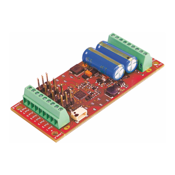
Image 1: Connections of motor, lighting front and rear, wheel set
Special functions A1 bis A8
The special function outputs A1 to A8 of the decoder are placed on the right screw terminal of the decoder (Image 1).
The power consumers connected to this terminal will be provided with current by the U+ terminal. You can fi nd detailed
information about all connections in the detailed instructin manual.
A short circuit in the area of the motor, lighting, pick-up wiper, or wheelsets can
SUSI interface
0
At the SUSI interface of the PIKO SmartDecoder 4.1 G you can either use a PIKO sound module with SUSI or a
suitable single-function decoder.
You can fi nd which CV should be programmed for its respective function output in the operating instructions.
The decoder is factory set to send data to the PIKO sound module via the SUSI interface.
* factory set values
and RailCom Plus
-ready and recognizes ABC automatic stop sections and ABC
®
®
motor
Input 3
white
M
Motor 1
yellow
Motor 2
red
Licht H
red
light
light
Licht V
black
front
rear
U +
Input 1
GND
red
Rad li.
black
Rad re.
Input 2
destroy the decoder and electronics of the model!
Lauts. A
SUSI
U +
Aux 1
Aux 2
Servo 1
GND
Aux 3
Aux 4
Servo 2
GND
Aux 5
Aux 6
Servo 3
GND
Aux 7
Aux 8
Servo 4
GND
Lauts. B
Advertisement

Related Manuals for PIKO SmartDecoder 4.1 G


Summary of Contents for PIKO SmartDecoder 4.1 G
- Page 1 0 - 4 ® At the SUSI interface of the PIKO SmartDecoder 4.1 G you can either use a PIKO sound module with SUSI or a 3 = CV 257 - 512 (extended function mapping banks 1 & 2) suitable single-function decoder.
- Page 2 In addition to the decoder address, the indexed CVs of a locomotive decoder are the most important CVs. These are the CVs 29, 50 and 51 in the PIKO SmartDecoder 4.1G. As a rule, an indexed CV contains various basic settings of a decoder, such as reversing the direction of travel.
Need help?
Do you have a question about the SmartDecoder 4.1 G and is the answer not in the manual?
Questions and answers