Trox FKRS-EU Installation And Operating Manual
Fire damper
Hide thumbs
Also See for FKRS-EU:
- Supplementary installation manual (28 pages) ,
- Installation and operating manual (288 pages)

Related Manuals for Trox FKRS-EU


Summary of Contents for Trox FKRS-EU
- Page 1 Installation and operating manual GB/en Fire damper Type FKRS-EU according to Declaration of Performance DoP / FKRS-EU / DE / 002 Read the instructions prior to performing any task!
- Page 2 TROX GmbH Heinrich-Trox-Platz 47504 Neukirchen-Vluyn Germany Phone: +49 (0) 2845 2020 Fax: +49 (0) 2845 202-265 E-mail: trox@trox.de Internet: http://www.trox.de Translation of the original M375EE7, 2, GB/en 11/2014 © 2014 Fire damper Type FKRS-EU...
- Page 3 This operating and installation manual enables oper- To ensure that a fault is processed as quickly as pos- ating or service personnel to correctly install the TROX sible, please keep the following information ready: product described below and to use it safely and effi- Delivery date of the TROX components and sys- ...
- Page 4 Warning – danger zone. Potentially hazardous situation which, if not avoided, may result in property damage. ENVIRONMENT! Environmental pollution hazard. Tips and recommendations Useful tips and recommendations as well as infor- mation for efficient and fault-free operation. Fire damper Type FKRS-EU...
-
Page 5: Table Of Contents
5.9.1 General..........46 FKRS-EU with fusible link......8 5.9.2 Fixing to the ceiling slab......46 FKRS-EU with spring return actuator..9 5.9.3 Fire dampers with fire batt..... 46 Transport and storage........11 Connecting the ductwork......... 49 Parts and function..........12 Ducts............ -
Page 6: Safety
TROX are not permitted. duties and to recognise and avoid potential dangers. Fire damper Type FKRS-EU... -
Page 7: Technical Data
EN 1751 Ventilation for buildings – Air terminal devices Declaration of Performance DoP / FKRS-EU / DE / 002 Temperatures may differ for units with attachments Data applies to uniform upstream and downstream conditions for the fire damper Rating plate... -
Page 8: Fkrs-Eu With Fusible Link
2.2 FKRS-EU with fusible link Dimensions and weight L = 400 ~ 180 ~ 75 Fig. 2: FKRS-EU with fusible link ① Keep clear to provide access for operation Weight [kg] Nominal size [mm] ØDN [mm] FKRS-EU with fusible link ... -
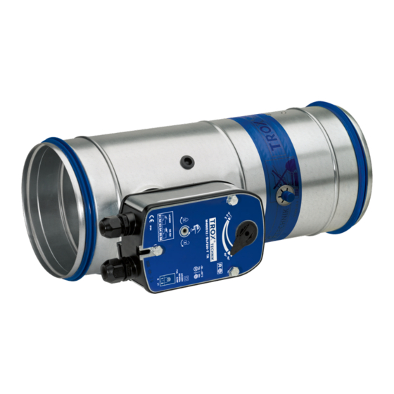
Page 9: Fkrs-Eu With Spring Return Actuator
2.3 FKRS-EU with spring return actuator Dimensions and weight L = 400 ~ 190 ~ 115 Fig. 3: FKRS-EU with spring return actuator ① Keep clear to provide access for operation Weight [kg] Nominal size [mm] ØDN [mm] FKRS-EU with spring return actuator ... -
Page 10: With Wall Face Frame
Technical data FKRS-EU with spring return actuator Weight [kg] Nominal size [mm] ... with square installation block (TQ) 10.6 11.5 12.4 13.8 15.5 17.6 ... with wall face frame (WA) 10.0 10.8 12.0 13.5 15.4 Spring return actuator BLF... Construction... -
Page 11: Transport And Storage
Do not expose the unit to the effects of weather (not even in its packaging). Do not store the unit below -40 °C or above 50 °C. Packaging Properly dispose of packaging material. Fire damper Type FKRS-EU... -
Page 12: Parts And Function
To ensure proper functioning of the fire damper, a test can be carried out. Ä 52 4.1 FKRS-EU with fusible link Fig. 5: FKRS-EU with spring return actuator ① Casing ② Temperature sensor ③ Damper blade with seal ④ Inspection access ⑤... -
Page 13: Installation
N = Mortar-based installation The class of performance depends on the installation details. E = Installation block or kit (ER, TQ, WA, GL) EQ = Installation block EQ W = Fire batt Fire damper Type FKRS-EU... -
Page 14: Safety Notes On Installation
Clean the fire damper. Remove transport and installation protection, if any. In case of mortar-based installation this protection must not be removed until the mortar has hardened. Test the function of the fire damper. Fire damper Type FKRS-EU... - Page 15 Installation General installation information > After installation Connect the ductwork. Make electrical connections. Fire damper Type FKRS-EU...
-
Page 16: Solid Walls
If the fire damper is installed as the wall is being erected, the perimeter gap »s« is not required. The open spaces between the fire damper and the wall must be closed off with mortar. Entrapped air is to be avoided. The mortar bed depth should be equal to the thickness of the wall. Fire damper Type FKRS-EU... -
Page 17: Dry Mortarless Installation With Circular Installation Block Er
Fix the cover plate with at least four M6 screws. For solid walls and solid ceiling slabs, suitable steel anchors with building inspectorate approval must be used. Dimensions of installation opening/cover plate [mm] Nominal size ØD1 ☐B Installation opening tolerance + 2 mm Fire damper Type FKRS-EU... -
Page 18: Dry Mortarless Installation With Fire Batt
Mineral wool strips ≥ 80 kg/m³ (only when distance ② Fire protection coating a≤ 50 mm) ③ Ⓐ Coated mineral wool slabs, ≥ 140 kg/m³ Installation side ④ Ⓑ Fire protection coating Operating side Note: Each fire damper must be suspended separately Ä 46. Fire damper Type FKRS-EU... - Page 19 Apply fire protection coating to joints, transitions, and any imperfections on the pre-coated mineral wool slabs. Apply fire protection coating, at least 2.5 mm thick, to the fire damper casing perimeter on both sides of the wall or ceiling slab. The actuator and release unit must not be coated. Fire damper Type FKRS-EU...
-
Page 20: Dry Mortarless Installation With Wall Face Frame Wa
Fix the wall face frame with four threaded rods M8 (push through installation) or with anchors. For solid walls, suitable steel anchors with building inspectorate approval must be used. Dimensions of installation opening/wall face frame [mm] Nominal size ØD2 ☐B2 Installation opening tolerance -20 mm / 2 mm Fire damper Type FKRS-EU... -
Page 21: Solid Ceiling Slabs
220 mm. Extend the fire damper with an extension piece or a spiral duct on the installation side. Close off the perimeter gap »s« with mortar. The mortar bed depth must be at least 100 mm. Fire damper Type FKRS-EU... - Page 22 If the fire damper is installed as the ceiling slab is being completed, the perimeter gap »s« is not required. Note: – Extend the fire damper with an extension piece or a spiral duct on the installation side. – Protect the inside of damper and the operating components/actuator, e.g. with plastic foil. Fire damper Type FKRS-EU...
-
Page 23: Dry Mortarless Installation With Circular Installation Block Er
Fix the cover plate with at least four M6 screws. For solid walls and solid ceiling slabs, suitable steel anchors with building inspectorate approval must be used. Dimensions of installation opening/cover plate [mm] Nominal size ØD1 ☐B Installation opening tolerance + 2 mm Fire damper Type FKRS-EU... -
Page 24: Dry Mortarless Installation With Fire Batt
Make sure that the distance from the connecting spigot on the operating side to the ceiling slab is 220 mm. Extend the fire damper on the installation side with an extension piece (either attachment or supplied by others). Fire damper Type FKRS-EU... -
Page 25: Mortar-Based Installation Into Concrete Bases
≥ 75 mm distance to load-bearing structural elements Attach the new fire damper to the old fire damper Create concrete base, for a reinforcement plan see Fig. 15. No reinforcement is required for bases with a height of ≤ 50 mm. Fire damper Type FKRS-EU... - Page 26 Fig. 15: Reinforcement plan for concrete base with a height of 500 mm or 750 mm ① Reinforcing steel ∅8 mm ③ Reinforcing steel ∅8 mm, mortared into the ceiling ② Reinforcing steel ∅6 mm slab with Hilti-HY200 or equivalent ④ Reinforcing steel ∅8 mm Fire damper Type FKRS-EU...
-
Page 27: Lightweight Partition Walls
The installation opening must be stabilised with a reinforcing section or with horizontal and vertical sections Additional layers of cladding or double stud systems are approved Duct connection with flexible connector (recommended) Fire damper Type FKRS-EU... - Page 28 TQ ☐B1 ☐A1 = ∅ DN + 80...800 mm + 2 × trim panel thickness Dry mortarless installation with fire batt Optional trim panels Installation opening tolerance +2 mm Trim panels are required Fire damper Type FKRS-EU...
-
Page 29: Mortar-Based Installation
Distance between two fire dampers [mm] class load-bearing Two installation open- One installation opening structural ele- ings (flange to flange) ments [mm] ≥75 ≥200 EI 120 S 100...200 – ≥40 ≥200 EI 90 S 100...315 40...60 Fire damper Type FKRS-EU... - Page 30 220 mm. If the wall thickness is >115 mm, extend the fire damper on the installation side with an extension piece or a spiral duct. Close off the perimeter gap »s« with mortar. Fire damper Type FKRS-EU...
- Page 31 F30 walls (W = 200 mm shown) optional ④ Perimeter metal section ⑤ Dry wall screw ⑥ Mineral wool (depending on wall construction) Installation details for other wall types are available on request Fire damper Type FKRS-EU...
-
Page 32: Dry Mortarless Installation With Square Dry Mortarless Installation Kit Tq
If the wall thickness is >115 mm, extend the fire damper on the installation side with an extension piece or a spiral duct. Fix the cover plate with at least four screws (dry wall screws ∅ ≥ 4.2 mm, a ≥ 10 mm) to the perimeter metal section. Fire damper Type FKRS-EU... - Page 33 ④ ⑫ Perimeter reinforcing board, 12.5 × 50 mm, Perimeter metal sections ⑤ Dry wall screw required only for F30 walls ⑥ Mineral wool (depending on wall construction) optional ⑦ Trim panels Fire damper Type FKRS-EU...
-
Page 34: Dry Mortarless Installation With Fire Batt
Coated mineral wool slabs, ≥ 140 kg/m³ a≤ 50 mm) ④ Ⓐ Perimeter metal section Installation side ⑤ Ⓑ Dry wall screw (for cladding) Operating side Ä 46. Note: Each fire damper must be suspended separately Fire damper Type FKRS-EU... - Page 35 Apply fire protection coating to joints, transitions, and any imperfections on the pre-coated mineral wool slabs. Apply fire protection coating, at least 2.5 mm thick, to the fire damper casing perimeter on both sides of the wall or ceiling slab. The actuator and release unit must not be coated. Fire damper Type FKRS-EU...
-
Page 36: Dry Mortarless Installation With Installation Kit Gl
≥ 50 mm distance to load-bearing structural elements ≥ 200 mm distance between two dry mortarless installation kits Subsidence of the ceiling slab a ≤ 40 mm For installation, follow the supplied installation manual. Fire damper Type FKRS-EU... -
Page 37: Fire Walls
Dry mortarless installation with square dry mortarless installation ☐B1 2, 3 kit TQ s = 40...60 mm Optional trim panels Trim panels are required, ☐A1 = ☐A + 2 x trim panel thickness Installation opening tolerance +2mm Fire damper Type FKRS-EU... - Page 38 Dry wall screw Ø 3.9 × 35 mm ⑤ ⑩ Carriage bolt, L ≤ 50 mm, with nut and washer UA connecting bracket; construction elements ⑥ Bracket according to manufacturer's instructions ⑪ Installation opening depending on installation type Ä on page 37 Fire damper Type FKRS-EU...
- Page 39 Dry wall screw Ø 3.9 × 35 mm ⑤ ⑩ Carriage bolt, L ≤ 50 mm, with nut and washer UA connecting bracket; construction elements ⑥ Bracket according to manufacturer's instructions ⑪ Installation opening depending on installation type Ä on page 37 Fire damper Type FKRS-EU...
-
Page 40: Mortar-Based Installation
220 mm. If the wall thickness is >115 mm, extend the fire damper on the installation side with an extension piece or a spiral duct. Close off the perimeter gap »s« with mortar. Fire damper Type FKRS-EU... -
Page 41: Dry Mortarless Installation With Square Dry Mortarless Installation Kit Tq
If the wall thickness is >115 mm, extend the fire damper on the installation side with an extension piece or a spiral duct. Fix the cover plate with at least four screws (dry wall screws ∅ ≥ 4.2 mm, a ≥ 10 mm) to the perimeter metal section. Fire damper Type FKRS-EU... -
Page 42: Shaft Walls
Option Ⓐ: Provide the installation opening in the metal support structure with support sections. – Option Ⓑ: After cladding the wall, create a square wall opening and brace it with a perimeter metal section. – Fire damper Type FKRS-EU... -
Page 43: A = Dn + 80
Installation Shaft walls Installation opening ☐A [mm] Installation type Nominal size ☐A = ∅DN + 80... 120 mm Mortar-based installation ☐A Dry mortarless installation with square installation block EQ 1 ☐B Installation opening tolerance +2 mm Fire damper Type FKRS-EU... -
Page 44: Mortar-Based Installation
220 mm. If the wall thickness is >115 mm, extend the fire damper on the installation side with an extension piece or a spiral duct. Close off the perimeter gap »s« with mortar. Fire damper Type FKRS-EU... -
Page 45: Dry Mortarless Installation With Square Installation Block Eq
If the wall thickness is >115 mm, extend the fire damper on the installation side with an extension piece or a spiral duct. Fix the cover plate with at least four screws (dry wall screws ∅ ≥ 4.2 mm, a ≥ 10 mm) to the perimeter metal section. Fire damper Type FKRS-EU... -
Page 46: Suspended Installation Of The Fire Damper
5.9.3 Fire dampers with fire batt 5.9.3.1 Horizontal duct Installation of the fire damper with a fire batt in hori- zontal ducts requires a suspension system on both sides of the wall. Fire damper Type FKRS-EU... - Page 47 2 to 20 mm, e.g. cap blind rivets or high strength Clamp, e.g. Hilti MP-MX, Valraven BIS HD 500, or rivets. The riveted connection must be air-tight. equivalent ⑦ Ⓐ L-section to EN 10056-1 60 × 30 × 5 mm Installation side Ⓑ Operating side Fire damper Type FKRS-EU...
- Page 48 2 to 20 mm, e.g. cap blind rivets or high strength Installation side Ⓑ rivets; the riveted connection must be air-tight. Operating side ⑥ Bracket, e.g. Hilti MM-B-30 or equivalent ⑦ 4 screw fixings (M8 screw with 2 washers and nut), suitable for the bracket Fire damper Type FKRS-EU...
-
Page 49: Connecting The Ductwork
in lightweight shaft walls with fire batt Fire damper Type FKRS-EU... -
Page 50: Cover Grille
224 and above. 6.5 Inspection access Type FKRS-EU fire dampers have an inspection access Ä Chapter 4 ‘Parts that is closed with a rubber stopper and function’ on page 12. The interior of the fire damper must remain accessible for maintenance work and cleaning. -
Page 51: Making Electrical Connections
Indicator lights or relays can be connected as long cables are fitted with plugs. This ensures quick and as the performance specifications are taken into easy connection to the TROX AS-i bus system. For con- consideration. nection to the terminals, shorten the connecting cable. 7.3 Equipotential bonding... -
Page 52: Functional Test
Damper blade position indicator fingers. The position of the damper blade is indicated by the ð The damper blade closes and the tab ② on position of the handle. the handle locks into the CLOSED position. Fire damper Type FKRS-EU... -
Page 53: Fire Damper With Spring Return Actuator
Power is supplied. The thermoelectric release is in order. The toggle switch is not being pushed. Damper blade position indicator The position of the damper is indicated by the pointer on the actuator. Fire damper Type FKRS-EU... - Page 54 The damper blade is CLOSED TROL or AS-interface meet all these requirements. For details on these products please refer to the TROX Fire Insert the crank handle ① into the opening for the and Smoke Protection catalogue. spring-winding mechanism. (The crank handle is clip-fixed to the connecting cable.)
- Page 55 (The crank handle is clip-fixed to the connecting cable.) Rotate the crank handle by approx. 90° towards the 'unlock' position until a click can be heard. ð The damper blade closes. Remove the crank handle. Fire damper Type FKRS-EU...
-
Page 56: Commissioning
CLOSED fire dampers Fire dampers which close while the ventilation and air conditioning system is running must be inspected before they are opened again in order to ensure Ä ‘Inspection’ on page 57. their correct function Fire damper Type FKRS-EU... -
Page 57: Maintenance
Only lubricate the lubricating points if the damper blade unit Ä ‘Functional test with automatic control unit’ cannot be opened or closed easily. Use only oil or on page 54. grease that is free of resins or acids. Fire damper Type FKRS-EU... -
Page 58: Replacing The Fusible Link
Remove the used fusible link. Insert the new fusible link. Put the fusible link holder back into the fire damper and fix it with screws ①. Carry out functional test. Fire damper Type FKRS-EU... -
Page 59: Inspection, Maintenance And Repair Measures
Functional test of the fire damper (with spring return actuator) Specialist personnel Function OK Damper blade closes Damper blade opens – Determine and eliminate the cause of the fault – Replace the spring return actuator – Repair or replace the fire damper Fire damper Type FKRS-EU... - Page 60 The functional reliability of fire dampers must be tested at least every six months. If two consecutive tests are successful, the next test can be conducted one year later. C = As required, depending on the degree of contamination Maintenance work Item to be checked Required condition – Remedial action if necessary Fire damper Type FKRS-EU...
-
Page 61: Decommissioning, Removal And Disposal
Disconnect the wiring. Remove the ducts. Close the damper blade. Remove the fire damper. Disposal For disposal, the fire damper must be disassembled. ENVIRONMENT! Dispose of electronic components according to the local electronic waste regulations. Fire damper Type FKRS-EU... -
Page 62: Index
Weight..............8, 9 Installation position............. 14 Installation protection..........49 Installation situations..........13 Lightweight partition walls with metal support structure and cladding on both sides......27 Lightweight partition walls with metal support structure and cladding on one side......42 Fire damper Type FKRS-EU... - Page 63 Fire damper Type FKRS-EU...
- Page 64 Fire damper Type FKRS-EU...
Need help?
Do you have a question about the FKRS-EU and is the answer not in the manual?
Questions and answers