Advertisement
Quick Links
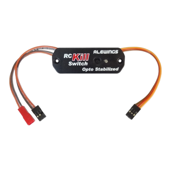
RC Kill Switch
Photocoupled electronic switch with
voltage regulator
USAGE MANUAL
Alewings
v. del Lavoro, 41 20084 Lacchiarella MI ITALY
www.alewings.it info@alewings.it
CONNECTIONS
FIXING:
Drill a rectangular hole of 53x23,5mm for placing the device.
Position and fix it with the 2 self-threading screws supplied.
It is recommended to realize an installation assuring the right
insulation from engine vibrations.
CONNECTION RC Kill Switch-Receiver:
Connect the 3 wires cable to the receiver into the channel you want
to use for controlling the Kill Switch.
The channel should correspond to a 2 position switch of the
transmitter with ATV and D/R set at 100%.
CONNECTION RC Kill Switch Spark ignition unit:
Connect the 2 wires cable with UNI connector (output of the switch)
to the spark ignition unit.
Connect the 2 wires cable with BEC connector (input of the switch)
to the battery you intend to use for supllying the spark ignition unit.
PICTURE 1
WARNING:
- Do not connect the Kill Switch to the receiver with inverted
polarity: connections with inverted polarity damage the device.
- Do not connect the battery to the Kill Switch with inverted polarity;
inversion of polarity damages the voltage regulator of the switch.
- Do not connect the Kill Switch output to the spark ignition unit with
inverted polarity; inversion of polarity may damage the spark
ignition unit and the voltage regulator of the device.
- Do not cause short circuits at the output of the switch: short circuit
damages the inner voltage regulator.
Cod. 90040210
®
di Alessandro Torri
External battery input
from 4.8V to 9V
Connect to engine
spark plugs
Connect to
magnetic sensor
Dear Customer,
thank you for your purchase of electronic switch RC Kill Switch.
It is an electronic switch for starting spark ignition of gasoline engines
V1.1
and it can be activated by the transmitter (a free channel is
needed) or by the button on the device itself; a high brightness LED
indicator shows the status of the device (ON/OFF).
The RC Kill Switch brings together an electronic switch, a voltage
regulator and a photocoupler that assures the insulation of the
receiver from electronic ignition interferences.
It is ready to use and any setting is required; anyway the user can
activate the fail safe function in case of loss of signal from the
receiver.
It needs a dedicated battery 4,8-9V and the output voltage can be
set by the user from 5 to 7,4V
USAGE
The RC Kill Switch is ready to use after you have fixed the device,
carried out the connections as shown into the "Connection"
paragraph and set the right output voltage for your engine unit.
(See the following 2 paragraphs)
When you turn the device on:
- if the FailSafe function is activated the LED emits 3 rapid flashes
- if the FailSafe function is not activated the LED emits 2 series of 3
rapid flashes.
For starting the engine use the switch on the transmitter or press the
button on the device.
The LED on indicates that the switch is closed and that it is supplying
the spark ignition of the engine.
Connect to
Spark ignition
ON/OFF
Button
Unit input
Blue LED
Connect to
receiver
Advertisement

Related Manuals for Alewings RC Kill

Summary of Contents for Alewings RC Kill
- Page 1 USAGE CONNECTION RC Kill Switch-Receiver: The RC Kill Switch is ready to use after you have fixed the device, Connect the 3 wires cable to the receiver into the channel you want carried out the connections as shown into the “Connection”...
- Page 2 ATV higher than +30% (it is recommended setting the ATV from transmitter at 100%). 760us 1000us 2000us 2290us 1500us RC Kill Switch not activated RC Kill Switch activated REST ZONE SWITCHING ZONE -30% +30% Minimum limit Maximum limit...
- Page 3 Turn the transmitter on and check that the control of the channel managing it is in rest position. Turn the receiver on and check the right flashes of the LED. For activating the RC Kill Switch you can act in 2 different ways: - Press the button on the device for at least 2 seconds - Move the control on your transmitter from the rest position to the commutation position and keep there for at least 2 seconds (if you are using a two position switch without return spring or a trimmer/slade, bring it back to the rest position).
- Page 4 FIXING 53mm 23.5mm Distance between the holes 60mm ACCESSORIES If you have to mount the device inside your model and you are not able to see the LED, you can use this optional accessory in order to bring the lighting indicator in a visible position. Positive (RED) Negative (BLACK) Connect to external led...
Need help?
Do you have a question about the RC Kill and is the answer not in the manual?
Questions and answers