AEZ GC-M02 Manual
Automatic microprocessor control panel for stand-by generator
Hide thumbs
Also See for GC-M02:
- Installation and maintenance manual (57 pages) ,
- Owner's manual (98 pages)

Related Manuals for AEZ GC-M02


Summary of Contents for AEZ GC-M02
- Page 1 GCM02 AUTOMATIC MICROPROCESSOR CONTROL PANEL FOR STAND-BY GENERATOR MANUAL OF: Maintenance FILE LAST ISSUE LANG. PAGE GCM02-M-USO-INGLESE.doc SDG/02 18/11/2005 Page 1 of 12...
- Page 2 USER MANUAL INTRODUCTION We congratulate with you for the purchase of the GC-M02 control panel to handle your generator unit. Throughout this manual you will appreciate the remarkable performances and the different applications granted by the high technology the control panel contains.
- Page 3 1. to know the operating principle of the unit; 2. to understand the control panel signals; 3. to handle it during the different service operations; 4. to carry out the basic checks necessary to ensure the efficiency of the generator itself. Technical or adjustment matters have not been considered.
- Page 4 CR, a generator unit contact maker and the module that controls the system. GC-M02 Fig. 1 UTILITY Supposing that the mains R is within the normal limits, the CR mains contact maker is closed therefore the utility is powered from the mains.
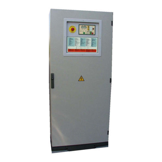
- Page 5 1.3 VIEW OF THE GC-M02 UNIT Programming switch: 1 Automatic test. (T) 2 Automatic running. (A) 3 Locked - logic disabled. 4 Forced power supply from mains (CR) Alphanumerical display showing all the 5 Manual starting enabled. parameters together with the literal description 6 Forced power supply from generator (CG).
- Page 6 1.4 FUNCTIONAL DESCRIPTION OF THE GC MO2 CONTROL PANEL COMPONENTS Description of the components. Programming switch. Type of operational mode selection 1. Automatic test (T) 2. Standard automatic running (A) 3. Locked status – electronics disabled, used for maintenance. 4. Utility power supply forced from mains (CR). 5.
- Page 7 The three phase voltages between one phase and another are displayed for the detailed control of the generator. and the three star voltages between phase and neutral The three phase currents are used to check the load status on the individual phase.
- Page 8 This block diagram indicates the status of the system which powers the utility. The trestle illustrates the public mains. The lit LED indicates that the three phases are within the fixed parameters and vice versa when it is switched off. The two CG and CR led indicate which contact maker is closed to power the utility.
- Page 9 1.5 CONTROLS AND OPERATING The operational modes that can be selected with the programming switch are six, namely: 1. Automatic test: This starts to test the generator without disconnecting the mains power supply from the utility. When the switch is turned back to automatic mode the generator stops following a delay of roughly one minute (it is used for periodic tests or to check the running efficiency after the maintenance).
- Page 10 EMERGENCY STOP If pressed, the red mushroom push button, placed in the middle of the door, stops the generator immediately and opens the contact maker of the generator (CG) causing the block of the group.. To release the emergency status, set the programming switch in Lock position, turn the emergency push button and pull it FUEL PUMP CONTROL (on request) The M02 module electronically controls the fuel level.
- Page 11 1.6 PROGRAMMING If the electronic module should be disconnected from the power supply, the established weekly timer programming will be deleted; consequently, all the functions foreseen for the internal timer would fail to work at the time and on the programmed day, therefore, the weekly timer has to be re-programmed.
- Page 12 REMOTE ASSISTANCE The group normally operates on automatic running and is remote-controlled. 1.9 SIMPLE MAINTENANCE OPERATIONS USER SAFETY PROCEDURE WARNING It is strictly forbidden to operate on parts under tension. ELECTRICAL MAINTENANCE All interventions must be carried out by skilled personnel. By means of the control unit, all control, check and reset functions are possible from the external .
Need help?
Do you have a question about the GC-M02 and is the answer not in the manual?
Questions and answers