Table of Contents
Advertisement
Quick Links
Other languages
http://net.grundfos.com/qr/i/96681360
Please read the Operation Manual completely and retain for future reference!
Damages resulting from operating errors cancel the guarantee.
®
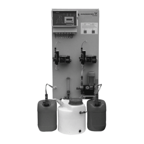
Oxiperm
C 164
Fully-automatic Chlorine Dioxide
Generation System
164 -4000C, -6000C, -7500C,
-10000C
Operation and Service Manual
1
Advertisement
Table of Contents

Related Manuals for GRUNDFOS ALLDOS Oxiperm C 164 Series


Summary of Contents for GRUNDFOS ALLDOS Oxiperm C 164 Series
- Page 1 ® Oxiperm C 164 Fully-automatic Chlorine Dioxide Generation System 164 -4000C, -6000C, -7500C, -10000C Operation and Service Manual Other languages http://net.grundfos.com/qr/i/96681360 Please read the Operation Manual completely and retain for future reference! Damages resulting from operating errors cancel the guarantee.
- Page 2 Oxiperm 164C 4-10 kg en Imprint ® Oxiperm C 164 fully-automatic chlorine dioxide generation system 164-4000C, -6000C, -7500C, -10000C Operation and Service Manual Issued by: ALLDOS Eichler GmbH Reetzstraße 85 • 76327 Pfinztal (Söllingen) Postfach 1160 • 76317 Pfinztal Tel. +49 72 40 61-0 / Fax. +49 72 40 61-211 Subject to change.
-
Page 3: Installation Data
Oxiperm 164C 4-10 kg en Installation data NOTE Please fill in this form following commissioning. It will help you and your Grundfos-Alldos servicing partner to adjust the device during subsequent corrections. Owner: ALLDOS customer No.: Contract No.: Order No. of device: Serial number of device: Put into service on: Location of device:... -
Page 4: Table Of Contents
Oxiperm 164C 4-10 kg en Contents Installation data ....................3 Installation diagram ..................3 General ....................7 Introduction ....................7 Using this Document ................. 7 Guarantee ....................7 Safety Information .................. 8 Use of the System ..................8 Obligations of Owner ................. 8 Avoidance of Danger ................ - Page 5 Oxiperm 164C 4-10 kg en Hydraulic Connection ................28 6.6.1 Bypass Line ................. 28 6.6.2 Supply Line for Chemicals ............28 6.6.3 Sampling Line for Chlorine Dioxide ..........28 6.6.4 Discharge Line for Suction Injector for Solution Tank ....28 Electrical Connection ................
- Page 6 Oxiperm 164C 4-10 kg en Operation of the System ............... 62 Auto / Manual ..................62 9.1.1 Automatic Mode ................62 9.1.2 Manual Mode ................64 Gauging of the Dosing Pump for HCl/NaClO2 ........65 9.2.1 Gauging of HCl ................66 9.2.2 Gauging of NaClO2 ..............
-
Page 7: General
Oxiperm 164C 4-10 kg en General 1.1 Introduction This Operation and Service Manual contains all information for safe operation of the described device. Should you require further information, or should problems occur which are not handled in sufficient depth in this document, please request the information directly from Grundfos-Alldos. -
Page 8: Safety Information
Oxiperm 164C 4-10 kg en Safety Information 2.1 Use of the System Oxiperm ® C 164 is used to generate a chlorine dioxide solution within the context of the possible applications described in this manual. WARNING Other applications are considered as non-approved, and are not permissible. -
Page 9: Technical Data
Oxiperm 164C 4-10 kg en Technical Data 3.1 General Data 3.1.1 Performance and Consumption Data Consumption of Dilution water requirement for bypass system System generation Op. pressure performance * components * Bypass Prelim. dilution Suction from Total water quantity NaClO2/HCl (with 3 g/l) for HCl solution tank... -
Page 10: Connection Data And Weights
Oxiperm 164C 4-10 kg en System Water required for bypass system Total water Bypass Bypass Bypass quantity at a (at 2 g/l) (at 3 g/l) (at 3,3 g/l) concentration of 2 g/l (l/h) (l/h) (l/h) (l/h) 164-4000C 1810 1150 1020 3400 164-6000C 2715... - Page 11 Oxiperm 164C 4-10 kg en Dimensions in mm. 15.710120-V6.0...
- Page 12 Oxiperm 164C 4-10 kg en V6.0...
-
Page 13: Electrical Data
Oxiperm 164C 4-10 kg en 3.2 Electrical Data Power consumption Order No. Power consumption (VA) 550 VA 164-4000C 550VA 164-6000C 550 VA 164-7500C 900 VA 164-10000C Max. permissible loading of floating output contacts 250 V / 6 A, max. 550 VA Max. -
Page 14: Fundamentals
Oxiperm 164C 4-10 kg en Fundamentals 4.1 Chlorine Dioxide for Water Treatment Properties of chlorine dioxide ❏ Strong and fast oxidation and disinfection agent ❏ Applications in the treatment of drinking, service, cooling and waste water ❏ Chemically unstable compound Can explosively decompose into chlorine and oxygen when heated Must be generated on site as required since storage in cylinders is not possible... -
Page 15: Functional Sequence
Oxiperm 164C 4-10 kg en ® According to the Oxiperm C 164 application, a multiple stoichiometric excess of hydrochloric acid is used for the following reasons: ❏ A non-critical chlorine dioxide concentration of 20 g ClO / l is generated in ®... -
Page 16: Design And Function
Oxiperm 164C 4-10 kg en Design and Function 5.1 System Design V6.0... - Page 17 Oxiperm 164C 4-10 kg en Legend: Dosing system for hydrochloric acid (HCl) Item Connection line (HCl) Item Suction pulsation damper or gauging system (HCl) Item Pulsation damper (HCl) Item Flowmeter + flow monitoring (HCl) Item Pressure retention valve or check valve (HCl) Dosing system for sodium chlorite (NaClO Item Connection line (NaClO2)
-
Page 18: Components
Oxiperm 164C 4-10 kg en Item Sampling line for ClO2 Item Emptying of solution tank Item Additional overflow contact 8 Suction injector for solution tank Item Injector Item Check valve Item Solenoid valve Item Solenoid valve for reactor purging unit Item Controller with display 5.2 Components... -
Page 19: Flowmeters
Oxiperm 164C 4-10 kg en 5.2.3 Flowmeters The individual flow quantities are set on the system using rotameters, and monitored by limit contacts. An alarm is triggered if the set limits are violated, and the system is switched off. The LEDs on the controller flowchart light up permanently if the flow quantities are correctly set (see Section "Control and display elements on the controller", item 1, item 3, item 4 and item 19). -
Page 20: Solution Tank For Clo2
Oxiperm 164C 4-10 kg en 5.2.7 Solution Tank for ClO2 The solution tank is also positioned at the rear of the system and serves as a pressure-free tank for the generated and diluted chlorine dioxide. The solution tank is also monitored by 5 different contacts: overflow, MAX, MIN and running dry are directly evaluated by the controller. -
Page 21: Options
Oxiperm 164C 4-10 kg en 5.2.12 Options Power supply Code Description V000 Power supply 230 V / 50 Hz V001 Power supply 115 V / 60 Hz Bypass Code Description B010 Bypass valves 230 V / 50 Hz (standard version) B011 Bypass valves 115 V / 60Hz Bus systems... -
Page 22: Mode Of Operation Of System
Oxiperm 164C 4-10 kg en 5.3 Mode of Operation of System When starting up the compact system, the centrifugal pump (5.2) is activated. The dilution water for the hydrochloric acid flows through the flowmeter (5.4). When the MIN contact is exceeded, the other system components are switched on, i.e. dosing pump for HCl / NaClO2 (3), solenoid valve for bypass (4.2) and the solenoid valve (8.3) for the suction injector. - Page 23 Oxiperm 164C 4-10 kg en You can find further general information for operation of a chlorine dioxide system in: Accident prevention regulations: "Chlorination of water" (VGB 65 or GUV 8.15) (German) Carl Heymanns Verlag, Cologne Directive on dangerous working materials (ArbeitsstoffV) in latest edition (German) DIN 19617 "Sodium chlorite solution for water treatment;...
-
Page 24: Installation
Oxiperm 164C 4-10 kg en Installation 6.1 Transport and Storage WARNING Heavy system! Only use suitable lifting and transport equipment! Only transport system when empty! ● Transport system carefully. ❏ Dry, cool storage location. Do not expose to direct sunlight! 6.2 Unpacking ®... -
Page 25: Installation Diagrams
Oxiperm 164C 4-10 kg en 6.4 Installation Diagrams 6.4.1 Installation Diagram for Water Supply and Connection of the Chemicals Water supply The water supply (1) is via an external line provided on site. The inlet pressure of the line should be approx. 4-5 bar. If the required pressure is not available, a booster pump (2) with shut-off fittings must be installed in the water supply line. -
Page 26: Installation Diagram For Sampling Of Clo2, Suction And Overflow
Oxiperm 164C 4-10 kg en Legend Item Supply water inlet Item Booster pump with shut-off fittings Item Inlet for NaClO2 Item Shut-off unit (ball valve) Item Suction line for NaClO2 with advanced empty alarm and empty alarm (not included in delivery) Item Inlet for HCl Item... -
Page 27: Floor Mounting Of System Frame
Oxiperm 164C 4-10 kg en 6.5 Floor Mounting of System Frame The installation material 553-690 includes mounting bracket, Fillister head screws, long-shank screws, plugs, washers and nuts. ● Secure the Oxiperm C164 system frame on the floor using the enclosed installation material. -
Page 28: Hydraulic Connection
Oxiperm 164C 4-10 kg en 6.6 Hydraulic Connection 6.6.1 Bypass Line ● The bypass water supply line is a PVC pipe. The pressure losses in the line must be taken into account with a very long line or a small cross-section. See Section 3.1.2 "Connection data"... -
Page 29: Electrical Connection
Oxiperm 164C 4-10 kg en 6.7 Electrical Connection WARNING The electrical connection must only be carried out by qualified personnel! Observe the local safety regulations! Danger to life! Switch off the power supply before connecting the mains cable! Power supply connection WARNING This must be disconnected from the power supply each time the system is connected. - Page 30 Oxiperm 164C 4-10 kg en Connection diagram 164-4000C to 164-10000C Power supply Power supply - input Power supply - output H2O centrifugal pump NaClO2/HCl dosing pump Solenoid valve: system emptying Solenoid valve: H2O purging Solenoid valve: bypass water Solenoid valve: tank suction Floating outputs Common NC contact...
- Page 31 Oxiperm 164C 4-10 kg en 15.710120-V5.0...
-
Page 32: Profibus/Ethernet (Option)
Oxiperm 164C 4-10 kg en 6.7.1 Profibus/Ethernet (Option) The controller of the Oxiperm C164 can be optionally equipped with Profibus or Ethernet. Profibus-DP module The Profibus-DP connection is made via a 6-pin plug (see Profibus connection diagram). DP +5V DP GND RxD/TxD-P RxD/TxD-N PGND... -
Page 33: Rs232 / Rs422 / 485 Interface
Oxiperm 164C 4-10 kg en 6.7.2 RS232 / RS422 / 485 Interface As a further option, the controller of the Oxiperm C164 can be equipped with interfaces. RS 232 See following Fig. for connection of the RS232 interface RS 422 / 485 See following Fig. -
Page 34: Operation Of Control Electronics
Oxiperm 164C 4-10 kg en Operation of Control Electronics 7.1 Program Structure Automatic mode Manual mode Logbook Main menu System Set up Service mode selection Type 1, Type 2, System type Language Venting etc. Operating Min. contact Auto / Manual Setting data mode water... -
Page 35: Control And Display Elements
Oxiperm 164C 4-10 kg en 7.2 Control and Display Ele- ments NaClO Legend Item LED - dosing controller for NaClO flow. LED on when MIN contact is exceeded Item LED for NaClO tank LED off, level OK LED flashes with advanced empty alarm LED on, empty alarm Item LED for bypass water. - Page 36 Oxiperm 164C 4-10 kg en Item LED for alarms LED on or flashing with alarm present Item Display of automatic or manual mode LED flashes: manual control LED on: automatic control Item LED for remote on/off mode LED flashes: remote on/off by MIN contact for main water LED on: remote on/off by external contact Item...
-
Page 37: Automatic Mode
Oxiperm 164C 4-10 kg en 7.3 Automatic Mode In automatic mode, the solution tank for chlorine dioxide is continuously filled between the MIN and MAX contacts. The system is switched off when the chlorine dioxide solution in the tank reaches the MAX contact. -
Page 38: System Selection
Oxiperm 164C 4-10 kg en 7.6 System Selection Define the system size and the operating mode in the "System selection" menu. You can cancel the input at any time using the "Escape" key. The activated system type or the activated mode is displayed flashing on the display. -
Page 39: Basic Setting
Oxiperm 164C 4-10 kg en 7.7 Basic Setting ● In the main menu, switch to the "Basic setting" menu using the "F2" key (scroll if necessary). 7.7.1 Language ● In the "Basic setting" menu, switch to the "Language" menu using the "F1" key. -
Page 40: Reset Function
Oxiperm 164C 4-10 kg en Switch to "Level 2 Parameters" using "F2" key. ● Activate input field using "F1" key. Input of code analogous to level 1. ● Use the "Enter" or "Escape" key to return to the "Code function" menu. ●... - Page 41 Oxiperm 164C 4-10 kg en Date setting Display: Current XX.YY.ZZ 15-04-02 2 Accept > ● Switch to the "Day of week" menu using the "Arrow right" key, and back to the "Date setting" menu using the "Arrow left" key Day of week Display: Current Monday...
-
Page 42: Bus Options
Oxiperm 164C 4-10 kg en 7.7.6 Bus Options ● Scroll in the "Basic setting" menu using the "Arrow right" and "Arrow left" keys. ● Switch to the "Bus options" menu using the "F2" key. Display: Bus options 1 Profibus DP 2 Modbus 3 No bus >... -
Page 43: Automatic Start
Oxiperm 164C 4-10 kg en 7.7.8 Automatic start This function is used to perform an automatic system restart, if the system’s bypass water supply becomes compromised as a result of pressure fluctuations (bypass water undershoots the MIN limit) or if the bypass water overshoots the MAX limit. The system will restart automatically following a set pause time. -
Page 44: Service Mode
Oxiperm 164C 4-10 kg en 7.8 Service Mode 7.8.1 Venting of Bypass Water Line and Dosing Pumps for NaClO2 / HCl and H2O Venting of bypass line In the main menu, switch to the "Service mode" menu using the "F3" key, or scroll in the main menu. -
Page 45: Setting Data
Oxiperm 164C 4-10 kg en Venting of HCl/NaClO2 pump In the "Service mode" menu, switch to the "HCl/NaClO2 pump" menu using the "F3" key. Display: HCl/NaClO2 pump 1 Pump <OFF> ● The "F1" key is used to activate and deactivate the pump for the chemicals. ●... -
Page 46: Test Mode
Oxiperm 164C 4-10 kg en ● Use the "F2" key (page 1) to switch to the "Bypass water" menu Bypass water Display: 164-xxxxxC Concentration x.x g/l Setpoint XXXX +/- XXX l/h This menu displays the set concentration and the bypass water required. The setpoint is calculated by the controller and must be set on the left flowmeter of the system using the dosing ball valve. -
Page 47: Reactor Temperature
Oxiperm 164C 4-10 kg en 7.8.4 Reactor Temperature In this menu it is possible to examine the current reactor temperature at any time. In the "Service mode" menu on page 2, use the "F1" key to switch to the "Reactor temperature"... -
Page 48: Startup
Oxiperm 164C 4-10 kg en Startup CAUTION It is absolutely essential to observe the following procedure when starting up Oxiperm C164 systems with concentrated chemicals: Selection of system and operating mode Checking of limit contacts on flowmeters Startup mode, filling of reactor with water Filling of the preliminary water tank Venting and adjustment of pump for H 2 O Venting and adjustment of pumps for HCl/... -
Page 49: Selection Of System And Operating Mode
Oxiperm 164C 4-10 kg en chemicals. It must be possible to assume that these persons complete their tasks reliably. ➜ See accident prevention regulation GUV 8.15 or VBG 65 "Chlorination of water" (German) Therefore startup must only be carried out by trained specialists using appropriate instructions. -
Page 50: Limit Contacts For 164-4000 C
Oxiperm 164C 4-10 kg en 8.2.1 Limit Contacts for 164-4000 C Flowmeter (item 1) H2O - bypass water MIN contact: Flowmeter (item 2) NaClO2 MAX contact: MIN contact: Flowmeter (item 3) MAX contact: MIN contact: Flowmeter (item 4) H2O - dilution for hydrochloric acid MAX contact: MIN contact: 8.2.2... -
Page 51: Limit Contacts For 164- 10000 C
Oxiperm 164C 4-10 kg en 8.2.4 Limit Contacts for 164- 10000 C Flowmeter (item 1) H2O - bypass water MIN contact: 2500 l/h Flowmeter (item 2) NaClO2 MAX contact: MIN contact: Flowmeter (item 3) MAX contact: MIN contact: Flowmeter (item 4) H2O - dilution for hydrochloric acid MAX contact: MIN contact:... -
Page 52: Filling Of Water Tank
Oxiperm 164C 4-10 kg en Note: It is important to carry out the rinsing procedure twice to guarantee that there is no air remaining in the reactor before it is run with chemicals and also that any air bubbles which could collect between or in the ceramic rings have been completely eliminated! 8.4 Filling of Water Tank In order to guarantee fault-free startup of the systems, the bypass water line must... - Page 53 Oxiperm 164C 4-10 kg en NOTE The ball valve (item 5.6) must always remain open during operation of the system so that the water tank is continuously filled. ● Activate the solenoid valve for the bypass (item 4.2) using the "F1" key. The preliminary water tank is then filled if water flows through the bypass line of the system, i.e.
- Page 54 Oxiperm 164C 4-10 kg en V5.0...
-
Page 55: Venting And Adjustment Of The H2O Pump
Oxiperm 164C 4-10 kg en 8.5 Venting and Adjustment of the H2O Pump Venting The water tank (item 5.1) must be full in order to vent the centrifugal pump (item 5.2, Fig. on page 53). ● Close ball valve, item 5.7 (dilution water line), and subsequently open slightly (rotate counterclockwise by approx. - Page 56 Oxiperm 164C 4-10 kg en ● Use the „Arrow right“ key to switch to the impeller meter correction display Display indicator: 2 H2O Pump <OFF> < new: current: XXX l/h YYY l/h 3 accept ● Use the „F2“ key to activate the bypass pump NOTE To set the new „actual value“, the bypass pump must be active for at least 20 seconds to receive the correct...
-
Page 57: Venting And Adjustment Of The Pump For Hcl/Naclo2
Oxiperm 164C 4-10 kg en 8.6 Venting and Adjustment of the Pump for HCl/ NaClO2 NOTE Venting of the dosing pump for HCl/NaClO2 is initially carried out with water. NOTE The dosing pump is time-controlled during the venting procedure, and then switches off automatically (runtime approx. - Page 58 Oxiperm 164C 4-10 kg en In the delivered state, the ball valves (item 2.2.3 and item 1.2.3, directly above the gauging systems) are pointing to the front; i.e. gauging system closed, see figure below, item 2. NOTE If the water in the gauging system is insufficient for the venting procedure, the gauging systems must be repeatedly refilled with water until the water flows through the flowmeters without bubbles!
- Page 59 Oxiperm 164C 4-10 kg en Adjustment of flow quantities for HCl and NaClO2 The water existing in the gauging systems must be removed before the gauging systems are filled with chemicals. NOTE Only fill gauging systems with chemicals when no more water is present! ●...
-
Page 60: Venting And Adjustment Of The Bypass Line
Oxiperm 164C 4-10 kg en 8.7 Venting and Adjustment of the Bypass line Select the "Service mode / Venting / Bypass line" menu (also see Section 7.8.1) Display: Venting 1 Bypass <OFF> 2 Suction <OFF> 3 Purging <OFF> ● Activate the solenoid valve for the bypass using the "F1" key (display <ON>) ●... -
Page 61: Filling The Overflow System On The Solution Tank
Oxiperm 164C 4-10 kg en 8.9 Filling the Overflow System on the Solution Tank The overflow on the solution tank must be filled with water before the system is operated with chemicals. ● Open screwed gland (item 2) ● Fill with water, approx. 150-200 mm (see Fig.) ●... -
Page 62: Operation Of The System
Oxiperm 164C 4-10 kg en Operation of the System NOTE The system size and the operating mode must be selected before a system can be started in a particular mode. Two different operating modes can be selected for the Oxiperm systems: ☞... - Page 63 Oxiperm 164C 4-10 kg en ● The logbook functions can be called using the "F3" key (Automatic start, page 1). Display: Logbook 1 Active alarms 2 Event list 3 Operating hours (see also Section 7.5 "Logbook") Use the "Escape" key to return to the "Automatic start" menu Switch to page 2 using the "Arrow right"...
-
Page 64: Manual Mode
Oxiperm 164C 4-10 kg en Switching on the system (START) In the main menu, switch to the "Automatic" menu using the "F1" key Auto: x.x g/l start ? Display: 1 Setting data 2 Level MIN-MAX 3 Logbook > ● Activate the system using the "Enter" key Display: Auto: x.x g/l... -
Page 65: Gauging Of The Dosing Pump For Hcl/Naclo2
Oxiperm 164C 4-10 kg en 9.2 Gauging of the Dosing Pump for HCl/NaClO2 The flow quantities of HCl and NaClO2 are set on the flowmeters. It is nevertheless possible to gauge the flow quantities during operation of the system. Gauging is carried out with the gauging systems, item 1.2 (HCl) and item 2.2 (NaClO2) which are located on the right and left of the dosing pump. -
Page 66: Gauging Of Hcl
Oxiperm 164C 4-10 kg en 9.2.1 Gauging of HCl ● Rotate ball valve (item 1.2.3) into position 3 (white mark points in direction of manual vacuum pump, see Fig. 2, page 65) ● Close ball valve (item 1.2.2) ● Use a stopwatch to determine the time required to dose a certain quantity of liquid (HCl ), and calculate the dosing rate. -
Page 67: Alarms/Errors
Oxiperm 164C 4-10 kg en 10 Alarms/Errors 10.1 10.1 Acknowledgment of an Acknowledgment of an 10.1 10.1 10.1 Acknowledgment of an Acknowledgment of an Acknowledgment of an alarm alarm alarm alarm alarm Example: alarm from NaClO 2 dosing controller The following is output on the display: A ON ACK 1/1 Dosing controller NaClO 2... -
Page 68: Faults
Oxiperm 164C 4-10 kg en 10.2 Faults Fault Cause Remedy LED for bypass water (pos. 3) > Upstream pressure or volume of > Check the upstream pressure flashes: there is too little or no water are too low or water supply >... -
Page 69: Error Messages Of Controller
Oxiperm 164C 4-10 kg en 10.3 Error Messages of Cont- roller No. Fault Cause Elimination Advanced empty alarm NaClO2 Level in tank Refill tank for NaClO2 too low Advanced empty alarm Level in tank Refill tank for HCl too low Empty alarm NaClO2 NaClO2 tank empty... - Page 70 Oxiperm 164C 4-10 kg en No. Fault Cause Elimination Preliminary H2O tank MAX-MAX Overflow level in preliminary tank Check float switch for H2O has been reached in tank Flow HCl min Dosing quantity too low Check dosing pump or dose rate Flow HCl max Dosing quantity too high...
-
Page 71: Fuses/Leds Of Controller
Oxiperm 164C 4-10 kg en 10.4 Fuses/LEDs of Controller SI 1 Backup fuse, solenoid valve for emptying system Slow-blow Fuse ø5x20 mm SI 2 Backup fuse, solenoid valve for H20 purging Slow-blow Fuse ø5x20 mm SI 3 Backup fuse, solenoid valve for bypass water Slow-blow Fuse ø5x20 mm SI 4 Backup fuse for NaClO2 dosing pump (NaClO2/HCl) -
Page 72: Maintenance
Oxiperm 164C 4-10 kg en 11 Maintenance NOTE According to the German accident prevention regulations GUV 8.15 and VGB 65 § 19 (2), chlorine dioxide systems must be regularly checked for safety, at least once a year and prior to every startup, by a specialist. -
Page 73: Dismounting And Cleaning The Valves
Oxiperm 164C 4-10 kg en 11.1.1 Dismounting and Cleaning the Valves A drop in performance of the dosing pumps may be because of contamination in the suction and pressure valves. DN 8 valves ● Unscrew the suction and pressure valves. ●... - Page 74 Oxiperm 164C 4-10 kg en DN 20 valves ● Unscrew the suction and pressure valves. ● Remove the screw part at the bottom, take out the seat and ball. ● Replace damaged parts. Mount correctly when refitting (see Fig.) NOTE When installing the valves in the dosing head, make sure that the flow direction is correct (arrow).
-
Page 75: Dismounting The Diaphragm Of The Dosing Pump
Oxiperm 164C 4-10 kg en 11.1.2 Dismounting the Diaphragm of the Dosing Pump The dosing diaphragm should be replaced for safety reasons after a maximum of 2000 operating hours. ● Insert the suction lines of the pumps into a water tank, and run the system until the dosing heads of the pumps have been well purged with water. - Page 76 Oxiperm 164C 4-10 kg en Spare parts set for dosing heads M251/M252 Order No. 553-253-6 Item Part No. Designation 54.001 Flat gasket, UNI blue 10.4700-351 DN8 valve 10.5805-400 Shaft diaphragm, TFM 1700 10.7400-351 DN8 valve 48.905-400 Label 48.1104-403 Insert for spare parts set Spare parts set for dosing heads M253 Order No.
-
Page 77: Maintenance Of Valves Of Reactor And Purging Line
Oxiperm 164C 4-10 kg en 11.2 Maintenance of Valves of Reactor and Purging Line WARNING! Prior to any maintenance work on the valves, purge the reactor with water until no more chlorine dioxide is present! NOTE Prior to maintenance work on the system, the solution tank must be emptied down to the MIN/MIN contact! The reactor purging remains active until the level in the solution tank has reached the MAX contact! - Page 78 Oxiperm 164C 4-10 kg en Item 321.2 Shut-off ball valve (reactor) Item 321.3 Shut-off ball valve (NaClO2) Item 321.4 Shut-off ball valve (HCl) Item 322 Shut-off ball valve (reactor) Item 490 Orifice for bypass water line Item 492 Flat gasket (part No. 54.142) Item 980 Orifice for pre dilution H2O Valve replacement...
-
Page 79: Checking Of Temperature Sensor
Oxiperm 164C 4-10 kg en 11.3 Checking of Temperature Sensor The temperature sensor should be checked for damage during the maintenance work. The temperature sensor is screwed into a holder, and therefore has no direct contact with the chlorine dioxide solution in the reactor. ●... -
Page 80: Maintenance Of The Suction Injector
Oxiperm 164C 4-10 kg en 11.4 Maintenance of the Suction Injector The suction injector consists of nozzle, diffuser and holder with diaphragm check valve. The sucked chlorine dioxide (ClO ) is mixed with the motive water in the diffu- ser, and transported to the disposal line. The diaphragm check valve prevents water from penetrating the PE line when the suction is switched off. - Page 81 Oxiperm 164C 4-10 kg en Checking of diaphragm check valve If there are leaks on the diaphragm check valve, check the seat and piston, and replace if necessary. ● Switch off the system, and close the ball valve in the discharge line so that no water can escape when opening the diaphragm check valve.
-
Page 82: Maintenance Of Valves On The Suction Pulsation Damper
Oxiperm 164C 4-10 kg en 11.5 Maintenance of Valves on the Suction Pulsation Damper During the maintenance work, also check the valves on the suction pulsation damper and the manual vacuum pump for HCl and NaClO2, and replace the valves if necessary. -
Page 83: Maintenance Of The Solution Tank For Clo2
Oxiperm 164C 4-10 kg en 11.6 Maintenance of the Solu- tion Tank for ClO2 During all maintenance work, the contacts of the solution tank (overflow, MAX, MIN and running dry contacts) should be checked for correct height. NOTE The overflow contact (LSHH) is preset and must not be shifted further up! The volume between the overflow contact and the tank cover serves as a safety volume for emergency... - Page 84 Oxiperm 164C 4-10 kg en Spare parts Item Part No. Designation System 12.5733 Float, PVC 164-4000C to -10000C 12.4736 Changeover contact 164-4000C to -10000C 12.3768-320 Absorption filter 164-4000C to -10000C 12.4908-410 Float switch 164-4000C to -10000C Changeover contacts The changeover contacts on the solution tank are connected differently: Running dry contact (LSLL) Terminal 1/2 NO contact...
-
Page 85: Details On The Components
Oxiperm 164C 4-10 kg en 12 Details on the Components 12.1 Water Unit Water unit, complete Part No. Designation System 12.6173-300 230V 50Hz 164-4000C / 164-6000C 12.6173-310 115V 60Hz 164-4000C / 164-6000C 12.6174-300 230V 50Hz 164-7500C / 164-10000C 12.6174-310 115V 60Hz 164-7500C / 164-10000C Components for the water unit Item... -
Page 86: Solenoid Valves For Purging And Suction Injector
Oxiperm 164C 4-10 kg en 12.2 Solenoid Valves for Pur- ging and Suction Injector Components Item Part No. Designation System 30.2.1 53.083-25-3/4 Screwed gland R 3/4"-DN20 30.2.2 53.10245-3/4 Solenoid valve 230 V 53.10249-3/4 Solenoid valve 115 V 12.3 Pump for Dilution Water 3 Pump for Dilution Water 3 Pump for Dilution Water 3 Pump for Dilution Water... -
Page 87: Pulsation Damper
Oxiperm 164C 4-10 kg en 12.5 Pulsation Damper The design of the pulsation damper is the same for both chemicals, only the labels (HCl / NaClO2) are different. Components Item Part No. Designation System 140.1/150.1 53.056-25 Insert unit DN20 140.2/150.2 53.058-25 Union nut DN20 140.3/150.3 10.6864-301 Pulsation damper... -
Page 88: Impeller Meter
Oxiperm 164C 4-10 kg en 12.6 Impeller Meter Components Item Part No. Designation System 200.1 53.058-25 Union nut DN20 200.2 12.6202-400 Insert unit DN20-G1/2" 200.3 12.6010-1 Flowmeter FHKU100 200.4 52.345 O-ring, Viton 12.7 Flow Limiter Components Item Part No. Designation System 910.7 54.027... -
Page 89: Water Tank For Preliminary Dilution
Oxiperm 164C 4-10 kg en 12.8 Water Tank for Preliminary Dilution Components Item Part No. Designation System 90.5 12.6192-300 Float valve 90.20 12.4908-410 Float switch 15.710120-V6.0... -
Page 90: Leakage Monitoring
Oxiperm 164C 4-10 kg en 12.9 Leakage Monitoring Components Item Part No. Designation System 12.4908-420 Float switch 53.058-32 Union nut 52.153-2 O-ring 10.3153-416 Pressure plate 53.058-50 Union nut 52.155-2 O-ring Circuit diagram The connection cable (item 4) is connected on site. The leak monitoring signals are not evaluated by the system controller, the signal monitoring is carried out on site. -
Page 91: Spare Parts Sets
Oxiperm 164C 4-10 kg en 13 Spare Parts Sets Order No. System Voltage 553-691 164-4000C / 164-6000C 230/115 V version 553-692 164-7500C 230 V version 553-693 164-7500C 115 V version 553-694 164-10000C 230/115 V version The spare parts sets contain: ●... -
Page 92: Current Setting Data
Oxiperm 164C 4-10 kg en 14 Current Setting Data System setting System type: 164-4000C 164-6000C 164-7500C 164-10000C Operating mode: Automatic mode (factory setting) Bus control Batch concentration: 3 g/l (factory setting) Set concentration [ g/l ] Set flow quantities Bypass water quantity: [ l/h ] NaClO2 flow: [ l/h ]... - Page 94 Declaration of conformity GB: EU declaration of conformity CZ: Prohlášení o shodě EU We, Grundfos, declare under our sole responsibility that the products My firma Grundfos prohlašujeme na svou plnou odpovědnost, že výrobky Oxiperm C-164, Oxiperm C-166, to which this declaration below relates, Oxiperm C-164, Oxiperm C-166, na které...
- Page 95 United Arab Emirates China Bombas GRUNDFOS Portugal, S.A. H-2045 Törökbálint, GRUNDFOS Gulf Distribution Rua Calvet de Magalhães, 241 Grundfos Alldos Phone: +36-23 511 110 P.O. Box 16768 Apartado 1079 Dosing & Disinfection Telefax: +36-23 511 111 Jebel Ali Free Zone P-2770-153 Paço de Arcos...
- Page 96 96681360 0519 ECM: 1260245 www.grundfos.com...
Need help?
Do you have a question about the Oxiperm C 164 Series and is the answer not in the manual?
Questions and answers