Advertisement
Table of Contents
- 1 Table of Contents
- 2 Index
- 3 Revision Index
- 4 Introduction
- 5 General Warnings
- 6 Description
- 7 Main Components
- 8 Mechanical Installation
- 9 Installation Procedure
- 10 Electrical Connection
- 11 External Installation Scheme
- 12 Rs485 Bus Connection
- 13 Marking and Serial Number
- 14 Electronic Board
- 15 Atex Certificate and Cesi Notification
- Download this manual
Advertisement
Table of Contents

Related Manuals for Start italiana XMT


Summary of Contents for Start italiana XMT
- Page 1 INSTALLATION MANUAL MAGNETOSTRICTIVE LEVEL PROBE...
-
Page 2: Table Of Contents
Nota: Start italiana Srl, in respect of its quality duty may modify its production and data shown into this manual. This manual cannot be copied, neither partially, without authorization. -
Page 3: Introduction
XMT rev.03 2015-04 - ENG INTRODUCTION This manual gives all the installation and use instructions for XMT level probes. GENERAL WARNINGS Before the installation and use of the equipment please carefully read the instructions given into this manual. The manufacturer is not responsible of any possible operation not mentioned into this manual. -
Page 4: Description
The magnetostrictive level transmitters are based on the principle named Wiedemann effect and enable continuous and highly accurate reading of liquids’ level. The XMT level transmitter consists of a microprocessor based electronic circuit placed inside one aluminum case head and a stainless steel shaft containing a wave guide placed inside the tank. -
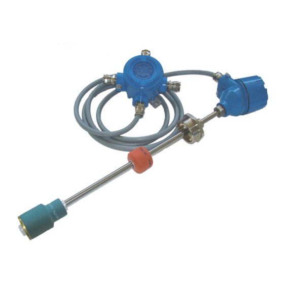
Page 5: Main Components
XMT rev.03 2015-04 - ENG MAIN COMPONENTS 1 Stainless steel shaft AISI 304 - Length from 200 to 6.000 mm 2 Sliding nipple 2” F gas nickel plated brass 3 Die-casted aluminium case IP68 4 Cable gland EExd ½”NPT IP68... -
Page 6: Mechanical Installation
The standard version of level probe XMT is supplied with a sliding 2” gas M fitting and the assembled floats enable to easily shift into 2” connection. This makes the probe insertion inside the tank easier,this means that no part of the probe must be disassembled for tank insertion operation. - Page 7 XMT rev.03 2015-04 - ENG Riser 2” as reinforce for the shaft external off the tank. Keep the sliding connection as near as possible to the head. At least 10 mm from the bottom IMPORTANT: if the probe is installed without leaving at least 10mm space from the bottom of the tank and blocked on the top with a sliding connection, any deformation of the tank that occurs will bend the probe compromising the correct functionality.
-
Page 8: Electrical Connection
It is recommended not to cut the cable for an easy extraction of the probe from the tank in case of maintenance. It is recommended the usage of junction box JB IP68 Exd supplied by Start Italiana under request. WARNING: the supplied 3 mt cable is moulded inside the probe head with special compound to improve the water proof;... -
Page 9: External Installation Scheme
XMT rev.03 2015-04 - ENG EXTERNAL INSTALLATION SCHEME The installation must be realized by specialized people Respect the safety rules Read carefully the instruction given into this manual The manufacturer is not responsible for any damage and/or supplementary costs due to the missing respect of the ... -
Page 10: Rs485 Bus Connection
RS485 BUS CONNECTION: Standard connection scheme of the probes to the bus RS485. Every probe is connected in parallel. If possible please use Start Italiana’s IP68 shunt boxes already equipped with connecting terminal. The 4 wires cable has always red-brown-blue-white colors. -
Page 11: Marking And Serial Number
Take note of the S.N. (ID address), it will be required during system recognizement through the set-up Software. On the cap head there is a metallic label with laser marking which is showing the following information: MARKING: Manufacturer: START ITALIANA SRL – 20813 Bovisio Masciago (MB) - Italy Type: XMT-XCR-XLR-DGM CE e O.N.: 0722 Group: II ½... -
Page 12: Electronic Board
XMT rev.03 2015-04 - ENG ELECTRONIC BOARD 4 = White 4 = White 3 = Blue 3 = Blue 2 = Brown 2 = Brown 1 = Red 1 = Red White Blue Brown Probe 1 Probe 2 Max no. of probes: 32... -
Page 13: Atex Certificate And Cesi Notification
XMT rev.03 2015-04 - ENG ATEX CERTIFICATE AND CESI NOTIFICATION... - Page 14 XMT rev.03 2015-04 - ENG...
- Page 15 XMT rev.03 2015-04 - ENG...
- Page 16 XMT rev.03 2015-04 - ENG...
- Page 17 XMT rev.03 2015-04 - ENG...
- Page 18 XMT rev.03 2015-04 - ENG...
- Page 19 XMT rev.03 2015-04 - ENG...
- Page 20 XMT rev.03 2015-04 - ENG...
- Page 21 XMT rev.03 2015-04 - ENG...
- Page 22 XMT rev.03 2015-04 - ENG...
- Page 23 XMT rev.03 2015-04 - ENG...
- Page 24 START italiana S.r.l. Via Pola, 6 20813 Bovisio Masciago MB Tel: +39 0362 15.81.465 Fax: +39 0362 15.81.464...
Need help?
Do you have a question about the XMT and is the answer not in the manual?
Questions and answers