Table of Contents

Related Manuals for iRZ 500 Series

Summary of Contents for iRZ 500 Series
- Page 1 IRZ 500 VARIABLE SPEED DRIVE «QUICK START» INSTALLATION MANUAL 2019...
-
Page 2: Table Of Contents
2.1 Operations with the drive controller ................... 7 3 PROCEDURE OF DRIVE OPERATION ....................13 3.1 Preparation of the drive ......................13 3.2 Emergency actions ........................15 ANNEX А - IRZ-500 MENU STRUCTURE ....................17 ANNEX B - RECOMMENDED IRZ-500 DRIVE CONNECTION DIAGRAM ..........18... -
Page 3: General Provisions For Work With The Product
IRZ 500 QUICK START 1 GENERAL PROVISIONS FOR WORK WITH THE PRODUCT 1.1 Safety measures 1.1.1 All dismounting, installation, start and adjustment works shall be performed according to the applicable “Safety Standards for Users of Electrical Installations” and “Maintenance Rules for Users of Electrical Installations”... - Page 4 IRZ 500 QUICK START Table 1.1 Recommended rated Total output power power of the (at rated input Main circuit connected motor (at Name voltage of 480 V and rated current, А rated input voltage of frequency of 50/60 480 V and frequency Hz), kV·А...
-
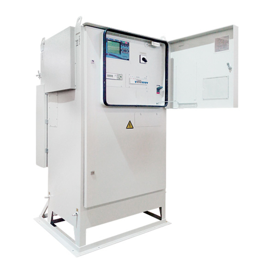
Page 5: Description Of Vsd Design
1.4.4 The operator’s panel is located inside a separate lockable compartment on the front side of the cabinet. 1.4.5 Design and operation of the control system 1.4.5.1 The control system consists of control units and IRZ-500 drive controller (hereinafter referred to as “controller”). 1.4.5.2 The operator’s panel includes the following controls and indicators: - Incoming power circuit breaker;... -
Page 6: Vsd Operation At Environment Temperature Variations
IRZ 500 QUICK START 1.4.5.3 The plate (fig. 1.1) on the operator’s panel of the IRZ-500 drive is for understanding the purpose of the automatic circuit breakers: “220V, 10A” receptacle To switch on the drive controller To switch on the drive lighting circuit... -
Page 7: Intended Use
IRZ 500 QUICK START 2. INTENDED USE 2.1 Operations with the drive controller Description of the main menu is given in Table 2.1. Table 2.1 Menu item Menu description MAIN REAL-TIME PARAMETERS Real-time condition of the drive, inverter and DHS... - Page 8 IRZ 500 QUICK START 2.1.2 "▲" and "▼" buttons are used to navigate between menu items and drive parameters, and to adjust control points values ("▲" – increase, "▼" - decrease). 2.1.3 "ENTER" button is intended to select certain menu item and to approve correctness of the value entered.
- Page 9 IRZ 500 QUICK START Table 2.2 – List of security profiles with allowed actions Access level Allowed actions WORKS ADMINISTRA OPERATOR ELECTRICIAN FOREMAN Profile access password No password Control points (settings) review** Control points change** SERVICE MENU contents review Full access to SERVICE MENU...
- Page 10 IRZ 500 QUICK START Table 2.4 – Drive and frequency inverter actual status codes Message on the drive’s Status description display The motor has been started and is now operating; the rotor catch mode may RUNNING be active PUSH The motor is running, the PUSH mode is active...
- Page 11 IRZ 500 QUICK START Status designation Event type Uab-Ubc IMBALANCE The motor has been stopped due to imbalance of Uab-Ubc voltage Uab-Uca IMBALANCE The motor has been stopped due to imbalance of Uab-Uca voltage Ubc-Uca IMBALANCE The motor has been stopped due to imbalance of Ubc-Uca voltage...
- Page 12 IRZ 500 QUICK START Status designation Event type MISSING COMMUNICATION WITH Motor cannot start because communication with the inverter INVERTER processor board via RS485 is missing Motor cannot start due to loss of supply voltage in the inverter INVERTER POWER LOSS...
-
Page 13: Procedure Of Drive Operation
IRZ 500 QUICK START Table 2.6 – Downhole sensor system actual state codes Message on the drive’s State description display NORM All signals coming from DHS are normally received by the drive MISSING COMMUNICATION Communication with the downhole sensor surface unit is missing... - Page 14 IRZ 500 QUICK START Group of settings Control point name Recommendations Nominal frequency of motor Max operating frequency of ESP unit. The value should correspond to the frequency for which the Step-up transformer secondary voltage is calculated. “INVERTER SETTINGS” Nominal voltage of inverter...
-
Page 15: Emergency Actions
IRZ 500 QUICK START 3.1.4 Check operation capability of surface equipment in idle mode (check the real-time parameters and protections). 3.1.5 Perform a test run of the drive in the manual control mode and monitor on the controller display that frequency is increased to 5 Hz. - Page 16 IRZ 500 QUICK START Check the insulation resistance control protection function for normal operation. If a downhole sensor system surface unit is not used, the DHS TYPE control point shall have the “NO” value; in the TRANSFORMER Y compartment of the drive, the XS12 connector shall be connected to VR210.
-
Page 17: Annex А - Irz-500 Menu Structure
IRZ 500 QUICK START ANNEX А - IRZ-500 MENU STRUCTURE « » "ESC" "F2" DHS STATUS DHS REAL-TIME REAL-TIME PARAMETERS *c an be acc ess ed PARAMETERS in cas e of fau lts « » Drive status Start/stop c ause Drive status Start/stop c ause «... -
Page 18: Annex B - Recommended Irz-500 Drive Connection Diagram
IRZ 500 QUICK START ANNEX B - RECOMMENDED IRZ-500 DRIVE CONNECTION DIAGRAM * Optional... - Page 19 IRZ 500 QUICK START Izhevskiy Radiozavod (IRZ) group of companies 19 Bazisnaya str., 426034 Izhevsk, Russia Manufacturer: IRZ TEK, LLC. Tel./fax.: +7(3412) 65-83-06 Tel.: +7(3412) 501-501 http:// www.irz.ru E-mail: sales@irz.ru Signed for printing on 04.03.2018...
Need help?
Do you have a question about the 500 Series and is the answer not in the manual?
Questions and answers