Table of Contents
Advertisement
Quick Links
Advertisement
Table of Contents

Related Manuals for GMW IPP 144-40 GS


Summary of Contents for GMW IPP 144-40 GS
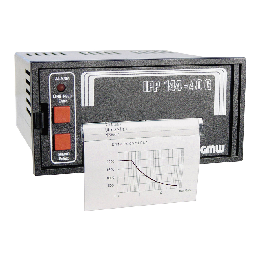
- Page 1 USER`S MANUAL Version 6.10.12 or higher Thermal Graphics Printers IPP 144 - 40 GS...
- Page 2 (EN 61010-1) Safety instructions In order to preclude any danger to the operator, the following instructions should be followed: In case any damage or malfunction is detected, take the unit out of operation without delay. Before disassembling the unit, disconnect all inputs / outputs and the supply voltage. When mounting the unit and the connections, make sure all live components are protected from being touched directly.
-
Page 3: Table Of Contents
SUMMARY Safety instructions Introduction First steps Function description Configuration Menu program Setting TTY (20 mA current loop) Pin assignment Menu program / Complete Selection Grafic print-out directly from WINDOWS ® Replacing the paper roll Possible errors Accessories Spare paper Cable Paper re-roll mechanism Plexiglass cover Appendix A: Design and installation... -
Page 4: Introduction
Transmission is serial by means of an RS 232 (V24) or TTY (20 mA current loop) interface. A 16 kByte data buffer allows rapid transmission. To format the text, IPP 144-40 GS supports the most important control characters of the siemens desktop printer PT88, e.g. bold, expanded. -
Page 5: Function Description
The printout is invented and right justified, which gives the correct order after the paper has been torn off. The IPP 144-40 GS starts the printing immediately after reception of <CR>. The control characters <CR>, <LF> and <FF> are print triggering characters. -
Page 6: Menu Program
Locking the Menu / Select If the jumper B is connected, the „MENU / SELECT“ key is locked; menu parameters can neither be printed or modified. In order to print or modify parameters: remove jumper B ! The key S102 resets the printer to the standby mode. The RESET -key menu parameters will not to be changed. - Page 7 Entering the Press the „Menu / SELECT“ key for approx. 3 s menu The IPP 144 reacts by printing program „ACTUAL PARAMETERS ? PRESS ENTER“ Print current Press the „ENTER“ key, parameters the IPP 144 prints the currently set parameters. The final printout says „CHANGE PARAMETERS ?“...
-
Page 8: Setting Tty (20 Ma Current Loop)
Quitting the The program is terminated by simultaneously menu pressing „ENTER“ and „SELECT“. program Following the printout „END“ all modified functions are saved. If there are no keys pressed over a period of approximately 2 minutes, the program is terminated automatically and any modifications made are not saved. -
Page 9: Menu Program / Complete Selection
Menu program / Complete selection SET INTERVAL NO ? NO PARITY YES ? >>> NO PARITY PRINTER ADDRESS NO ? SET INTERVAL 00 h 00 min 00 sec YES ? 00 h 00 min _0 sec PRINTER ADDRESS 00 h 0_ min 50 sec 00 h _4 min 50 sec 0_ h 34 min 50 sec _2 h 34 min 50 sec... -
Page 10: Grafic Print-Out Directly From Windows
Print graphics directly from WINDOWS ® It is possible to print graphics, such as bmp-, jpg- or tif-, directly from WINDOWS ® programs. Use a 24-pin type WINDOWS printer. ® The following configurations have been verified: INTERFACE: EMUL.EPS.LQ580 ESC/P2 WINDOWS printer driver: Epson Compatible 24 PIN and Epson LQ560 ®... -
Page 11: Replacing The Paper Roll
Replacing the paper Roll Proceed as descibed below: 1. For devices with a.c. powersupply be very careul. Warning: Dangerous voltage is accessible if replacing the paper roll after opening of the front panel ! 2. Push the snap lock to the right hand side and open the front panel. -
Page 12: Possible Errors
Possible errors If there is no printout or if the printout is incorrect, verify the following: - Has the paper run out? The end of paper is indicated by the „Alarm“ LED. - Did you insert the paper properly? - Do the baud rate, parity and word length of both units correspond? - Is the data cable disconnected? Does the pin assignment correspond to the description? - Is the setting „RS232/TTY“... - Page 13 The paper re-roll device is a DIN-specifiction panel mounting unit. It is supplied with power and controlled via the connector cable which comes with the unit. An LED indicates ready status. Depending on the distance between the two units at least the last 9 lines printed remain visible. The paper re-roll device is inserted into the panel cut-out from the front and is clamped against the rear side of the switchborad using the lateral mounting bolts.The switchboard thickness must not exceed 12mm.
- Page 14 Installation Make sure that the unit is properly mounted before connection and power on. Operation Use the handle (4) to pull out the front panel (1). ♦ Removing the paper Remove the holder (3) with the paper from roll body, ♦...
- Page 15 Technical Data Motor with friction clutch, electronic lag 3 sec Winding Paper width: max. 80 mm Paper length: max. 15 m Store temperature range: -20 °C to +80 °C Ambient Operating temperature range: 0 °C to +70 °C conditions Climate: relative humidity <...
-
Page 16: Plexiglass Cover
Plexiglass cover - The plexiglass cover allows IP64 protection. It is latched on the front panel of the device. Item number 27863 15940 - Dimensions: 155 x 155 mm - Material: Plexiglass and Santoprene 101-80 caoutchouc... -
Page 17: Appendix A: Design And Installation
Appendix A: Design and installation Design Paper and cutting edge alarm contact Key: LINE / FEED / Enter (paper end only version E) Key: MENU / Select Snap lock Alarm LED (paper end indicator) 10 Mounting screws Serial interface 11 Protective conductor Interface II (only version E) connection. -
Page 18: Appendix B: Technical Data
Installation The IPP 144 - 40 G fits into a DIN standard panel cut out. It is inserted into the switchboard opening from the front side and is fixed against the switchboard rear using mounting screws. The switchboard thickness must not exceed 12 mm. Appendix B: Technical data Type of printing Fixed head thermal line... -
Page 19: Paper
Type commercial grade, Paper document proof thermal paper Width 80 mm (+0 / -1 mm) Length approx. 14 m (approx. 4.600 line up to 48 characters per line) Max. outer roll diameter 40 mm Min. inner roll diameter 11,5 mm Temperature standard paper: 0 °C to 60 °C Serial... -
Page 20: Standards
Standards Protection type acc. to EN 60529/VDE 0470 housing IP 50 terminals IP 00 Insulation group C acc. to VDE 0110 Mech. strength acc. to IEC 1010 Emission EN 55011, Class A EN 55022, Class B Susceptibility EN 61000-4-2 B EN 61000-4-3 A EN 61000-4-4 B Voltage supply connector Screw type/terminals... -
Page 21: Appendix D: Connections
Appendix D: Connections The support of the XON/XOFF protocol depends on the PC (or PG) software. This handshake is necessary if more than 100 lines are to be transmitted at one time (4k/40) and is not possible with transmission mode TTY. RS232 PC - PG 25 pin and CP 521 B... - Page 22 TD/OP 15 pin TD/OP 9 pin 15 pin Socket P i n s Pins Socket Sig. GND Protection Only with XON/XOFF protocol CP 524 and CP 525 25 pin 9 pin 25 pin Socket P i n s Pins Socket Sig.
-
Page 23: Tty
passive DAA 25 pin IPP passive DAA active 9 pin 25 pin Socket P i n s Pins Socket RXD+ CST+ 5V 20mA CST- Sig. GND OP/TD 15 pin IPP passive TD/OP active 9 pin 15 pin Socket P i n s Pins Socket RXD+... -
Page 24: Appendix E: Control Characters
Appendix E: Control characters Print commands Line feed Carriage return ESC J n Prints and feeds paper ESC d n Prints and feeds paper by n lines Print character commands ESC - n Specifies/clears underline GS ! n Specifies character size Print position commands ESC $ nL nH Specifies absolute position... -
Page 25: Print Character Commands
Carriage Command: CR << Code >> return 0x0D << Function >> Executes the same action as (LF: „Line feed“) if auto line feed is effective. This command is ignored if auto line feed is not effective. Prints and Command: ESC J n <<... - Page 26 Specifies Command: GS ! n << Code >> character size 0x1D , 0x21, n (initial value n=0, Value see table) << Function >> Specifies character size ( vertical and horizontal magnification) Function Value vertical see Table 2 magnification Horizontal see Table 1 magnification Table 1 Bit7...
-
Page 27: Print Position Commands
Print position commands Specifies Command: ESC $ nL nH << Code >> absolute 0x1B , 0x24, nL , nH (0≤nL≤255 , 0≤nH≤255) position << Function >> Specifies the next print start position as an absolute position based on the left margin position. The next print start position is (nL + nH x 256) dots away from the left margin position. -
Page 28: Bitmap Image Commands
Bitmap image commands Commandl: ESC *m nL nH d1~dk Prints column << Code >> bitmap image 0x1B , 0x2A , m , nL , nH , d1~dk where: m=0, 32, 0≤nL≤255 , 0≤nH≤3, 0≤d≤255 << Function >> Specifies a bitmap image in mode m for the number of dots specified by nL and nH. - Page 29 Bitmap-Data format Col.1 Col.2 Col.n ..d 3n-2 ..d 3n-1 ..d 3n d 3(n+1)-2 d 3(n+2)-2 ..d 6n-2 d 3(n+1)-1 d 3(n+2)-1 ..d 6n-1 d 3(n+1) d 3(n+2) ..d 6n Prints raster Command: ESC A* nL nH d1~ dk <<...
-
Page 30: Line Feed Commands
The format of bitmap data for a printer with n heating elements in the head is as follows: ..d (n/8) d (n/8)+1 d (n/8)+2 d (n/8)+3 ..d (2n/8) d (2n/8)+1 d (2n/8)+2 d (2n/8)+3 ..d (3n/8) ..Line feed commands Command: ESC 2 Sets initial... -
Page 31: Barcode Commands
Barcode commands Selects Command: GS H n << Code >> printing 0x1D , 0x48 , n (0≤n≤3, initial value n=0) position of HRI character << Function >> Selects the print position of HRI characters when printing a barcode. << Details >> HRI refers to Human Readable Interpretation. - Page 32 Command: GS k n (Start) <data>NUL Prints << Code >> barcode 0x1D , 0x6B , n,(Start)<data> 00H (0≤n≤7) << Function >> Selects a barcode system and prints barcodes. In the case of GS k n: START BYTE BAR CODE TYPE No Start-Byte UPC-A No Start-Byte...
-
Page 33: Used By The Printer
General purpose characters Character Significance Name Ctrl D End of transmission Ctrl E Set address Ctrl J Line feed Ctrl M Carriage return Ctrl Q Ready to receive Ctrl S Busy XOFF Additional characters used by the printer Ctrl F 48 character / line Ctrl R 24 character / line... - Page 34 The following character set is used:...
- Page 35 Character set: ASCII and cyrillic it means: 1.Column = ASCII / 2. Column = cyrillic / 3. Column = Hexadecimal...
- Page 36 Hampshire RG26 5BH, U.K. Tel. +44 (0)845 03 43 234 Fax: +44 (0)845 03 43 233 E-mail:sale@metrix-electronics.com Web:www.metrix-electronics.com Gilgen, Müller & Weigert (GMW)GmbH & Co.KG Am Farrnbach 4A • D-90556 Cadolzburg Germany Telefon +49(0)9103 7129-0 Telefax +49(0)9103 7129-207/205 E-mail: info@g-mw.de • Internet: www.g-mw.de We reserve the right to make alterations ! 02.15...
Need help?
Do you have a question about the IPP 144-40 GS and is the answer not in the manual?
Questions and answers