Advertisement
Quick Links
Advertisement

Related Manuals for Jinhan JDS6052S


Summary of Contents for Jinhan JDS6052S
- Page 1 User manual JINHAN JDS6052S...
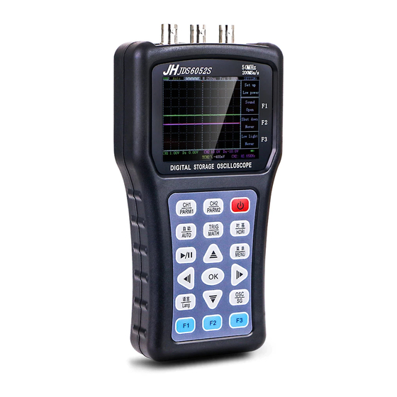
- Page 2 Exterior:...
- Page 3 Description of the oscilloscope display interface: Description of the oscilloscope button: As shown in the figure below, there are 18 oscilloscope buttons in the product: CH1/PARM1, CH2/PARM2, TRIG/MATH, 时基/HORI, 菜单/MENU These buttons are menu selection buttons, Their specific functions are as follows: Click CH1 / PARM1 to enter the control interface of CH1...
- Page 4 In this interface, the following buttons have the following features: F1: Control channel 1 is displayed or turned off F2: Select gear position of probe: x1, x10, x100 F3: Select the coupling mode of channel 1 as DC or AC ↑: Increase the size of the channel 1 unit grid representation (5V-10mV) ↓: Reduce the size of the channel 1 unit grid representation (5V-10mV)
- Page 5 In this interface, the following buttons have the following features: F1: invalid F2: invalid F3: invalid ↑: Increase the size of the channel 1 unit grid representation (5V-10mV) ↓: Reduce the size of the channel 1 unit grid representation (5V-10mV) ←: Move the channel 1 arrow down →: Move channel 1 arrow up Description: The displayed parameters have maximum, minimum, duty...
- Page 6 ↓: Reduce the size of the channel 2 unit grid representation (5V-10mV) ←: Move the channel 2 arrow down →: Move channel 2 arrow up Click CH2 / PARM2 again to enter the parameter display interface of In this interface, the following buttons have the following features: F1: invalid F2: invalid F3: invalid...
- Page 7 In this interface, the following buttons have the following features: F1: Control the trigger slope to rise or fall F2: Select the trigger source as CH1 or CH2 F3: Select the trigger: mode as automatic, normal or single ↑: Invalid ↓: invalid ←: Move the trigger arrow down →: Move the trigger arrow up...
- Page 8 In this interface, the following buttons have the following features: F1: Whether to display the MATH waveform F2: Select the function of MATH: CH1+CH2, CH1-CH2 or CH2-CH1 F3: Choose whether the display mode is YT mode or XY mode ↑: invalid ↓: invalid ←: invalid →: invalid...
- Page 9 F2: Select the calibration target line to be CH1, CH2, Ref-A or Ref-B F3: Select the type of auxiliary ruler line is time or voltage ↑: Reduce time base (5s - 12.5ns) ↓: Amplify time base (5s - 12.5ns) ←: Move the time base arrow to the left →: Move the time base arrow to the right Click the “时基/HORI”...
- Page 10 Click the “菜单/MENU” button once to enter the waveform storage interface. In this interface, the following buttons have the following features: F1: Select to store the waveform to A or B F2: Select the stored source as CH1 or CH2 F3: Whether to display the stored waveform ↑: invalid ↓: invalid...
- Page 11 In this interface, the following buttons have the following features: F1: Select backlight brightness F2: Select language type F3: invalid ↑: invalid ↓: invalid ←: invalid →: invalid Click the “菜单/MENU” button for the third time to enter the setting interface.
- Page 12 F1: Control button sound is on F2: Select the time for automatic shutdown F3: Select the level of power saving ↑: invalid ↓: invalid ←: invalid →: invalid Click the “Menu/Menu” button for the fourth time to enter the settings interface.
- Page 13 Click the “菜单/MENU” button for the fifth time to enter the reverse interface. In this interface, the following buttons have the following features: F1: Oscilloscope self-calibration F2: Whether CH2 turns on the inversion F3: Whether CH1 turns on the inversion ↑: invalid ↓: invalid ←: invalid...
- Page 14 F1: Choose whether to enable the screenshot function F2: Choose the name of the saved image F3: invalid ↑: invalid ↓: invalid ←: invalid →: invalid Description: When the screenshot function is enabled, pressing the OK button will take a screenshot. When the screenshot function is off, pressing the OK button is the function to save the waveform.
- Page 15 Switch the functions of the oscilloscope and signal generator. Note: In the off state, press the power button and OK button at the same time. The oscilloscope will enter the U disk mode. The Description of Signal generator interface: Description of the signal generator button: F1: Select frequency function or offset function F2: Select the type of output waveform F3: Select amplitude function or duty cycle function...
- Page 16 press the power button, it will enter the U disk mode, insert usb to connect to the computer, the U disk will appear, first format the U disk, copy the upgrade file update.bin Press the menu / MENU button to upgrade.
- Page 17 Automatic detection: 50 Hz – 20 MHz Cursor measurement: Time, voltage (manual mode) Recordable contrast waveform: 2 Screenshot function: stand by Mathematical calculation: CH1+CH2, CH1-CH2, CH2-CH1 Self-calibration: stand by Signal generator The number of channels: 1 Frequency: Sine wave (1 Hz – 5 MHz); Square wave (1 Hz – 1 MHz); Positive sawtooth wave (1 Hz –...
Need help?
Do you have a question about the JDS6052S and is the answer not in the manual?
Questions and answers
Driver de comunicação com pc