
Related Manuals for MaxLinear MxL7225


Summary of Contents for MaxLinear MxL7225
- Page 1 MxL7225 25A Dual Phase EVB User Manual MaxLinear Confidential • www.maxlinear.com • 006UMR02 TBD/18 006UMR02...
- Page 2 MxL7225 25A Dual Phase EVB User Manual Revision History Revision History Document No. Release Date Change Description 006UMR02 10/5/20 Initial release. 10/5/20 006UMR02...
-
Page 3: Table Of Contents
MxL7225 25A Dual Phase EVB User Manual Table of Contents Table of Contents Introduction................................. 1 Quick EVB Set Up and Start Up ............................1 Factory Settings ..............................1 Quick Start Up ..............................1 Reference Documentation ..........................4 Ordering Information............................4 Evaluation Board Overview ..........................5 Configuration and I/O Interfaces ........................ - Page 4 List of Figures Figure 1: Monitoring V and V ............................2 Figure 2: Top View of MxL7225 25A Dual Phase BGA EVB....................3 Figure 3: Block Diagram MxL7225 Two Channel EVB......................5 Figure 4: Load Transient Circuit .............................9 Figure 5: Mode 1 Block Diagram ............................11 Figure 6: Mode 2 Block Diagram ............................11...
- Page 5 MxL7225 25A Dual Phase EVB User Manual List of Tables List of Tables Table 1: Evaluation Board Ordering Part Number........................4 Table 2: Factory Settings................................7 Table 3: J44 Options ................................7 Table 4: J30, J29 Options...............................7 Table 5: J26 Options ................................7 Table 6: J25 Options ................................8 Table 7: JP45 Options ................................8...
-
Page 6: Introduction
In addition to utilizing the 4.5V to 15V input voltage range and dual 25A maximum load current rating capabilities of the MxL7225 Power Module, the Evaluation Board has been set up with the factory default configurations shown below for quick set up and operation. Do not exceed the EVB maximum load current rating. -
Page 7: Figure 1: Monitoring Vin
MxL7225 25A Dual Phase EVB User Manual Quick EVB Set Up and Start Up Load Load Figure 1: Monitoring V and V 10/5/20 006UMR02... -
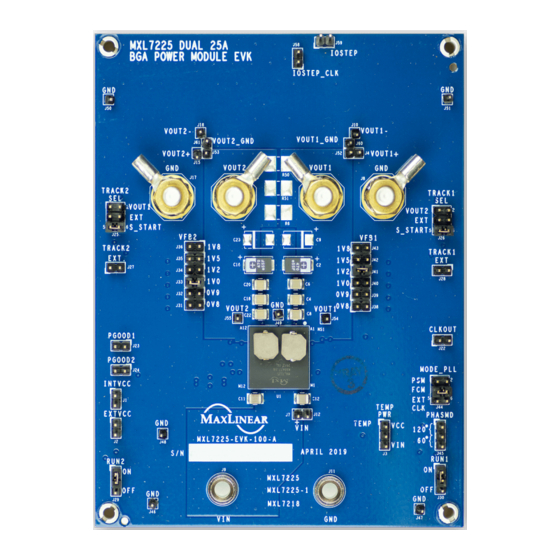
Page 8: Figure 2: Top View Of Mxl7225 25A Dual Phase Bga Evb
MxL7225 25A Dual Phase EVB User Manual Quick EVB Set Up and Start Up Figure 2: Top View of MxL7225 25A Dual Phase BGA EVB 10/5/20 006UMR02... -
Page 9: Reference Documentation
Reference Documentation Please refer to the MxL7225 Data Sheet for additional information about the MxL7225, including efficiency curves for this configuration with V = 12V. The datasheet also includes a full list of IC features, pinout, pin descriptions, typical performance characteristics and external component calculations. This manual is meant to be used in conjunction with the datasheet. -
Page 10: Evaluation Board Overview
MxL7225 25A Dual Phase EVB User Manual Evaluation Board Overview Evaluation Board Overview The block diagram shown in Figure 3 illustrates the connection points for the VIN, VOUT1, VOUT2, TRACK, MODE_PLL and RUN pins. VOUT1 CONNECTOR CONNECTOR VOUT1 TRACK1 (J26) -
Page 11: Configuration And I/O Interfaces
MxL7225 25A Dual Phase EVB User Manual Configuration and I/O Interfaces Configuration and I/O Interfaces MODE The MODE (J44) jumper is provided for overall device configuration: Force Continuous Mode, Pulse-Skipping Mode and External Synchronization are selectable. RUN1, RUN2 A RUN jumper is provided for both channels (J30 for RUN1 and J29 for RUN2). -
Page 12: Set-Up Options
MxL7225 25A Dual Phase EVB User Manual Set-Up Options Set-Up Options Jumpers are factory installed per Table 2 to configure the EVB for operation. Jumper and testing options are described in the next sections. Refer to the product datasheet for additional information. -
Page 13: Jumper J25 Track2 Sel
MxL7225 25A Dual Phase EVB User Manual Jumper J25 TRACK2 SEL Jumper J25 TRACK2 SEL Table 6: J25 Options Jumper Options Description Jumper 1-2 master track mode. OUT1 Jumper 3-4 External master track mode. Jumper 5-6 Soft start. Track1 connected to cap to GND. -
Page 14: Test Interfaces
MxL7225 25A Dual Phase EVB User Manual Test Interfaces Test Interfaces Load Transient Circuit A load transient circuit is provided to allow optional testing of load transients. The IOSTEP clock input is used to drive the transient signal. The load step generated by the FET (Q1) is very fast; the step slew rate is >40A/µs for a 12.5A transient load test case. -
Page 15: Mxl7225 Evb Mode Selection
MxL7225 25A Dual Phase EVB User Manual MxL7225 EVB Mode Selection MxL7225 EVB Mode Selection The MxL7225 EVB can be configured for 6 different modes of operation: ■ Mode 1: Dual 25A with no remote sense amplifier ■ Mode 2: Dual 25A with remote sense amplifier on V OUT1 ■... -
Page 16: Figure 5: Mode 1 Block Diagram
MxL7225 25A Dual Phase EVB User Manual MxL7225 EVB Mode Selection MODE2 MODE1 Dual Rail Single Phase Dual Rail Single Phase Diff Amp -> VOUT1 Diff Amp -> NC VOUT1+ VOUT1+ VOUT1 VOUT1 VOUTS1 VOUTS1 VOUT1- VOUT1- DIFFP DIFFP DIFFN... -
Page 17: Performance
MxL7225 25A Dual Phase EVB User Manual Performance Performance Efficiency , 1.5V , 1.5V Load Current (A) Figure 11: Channel 1 Measured Efficiency (V = 1.5V, f = 500kHz, Ch 2 Disabled) , 1.0V , 1.0V Load Current (A) Figure 12: Channel 2 Measured Efficiency (V = 1.0V, f... -
Page 18: Load Transient Response
MxL7225 25A Dual Phase EVB User Manual Load Transient Response Load Transient Response Figure 13: Load Transient Response (V = 1.5V, V = 12V) Figure 14: Load Transient Response (V = 1.0V, V = 12V) 10/5/20 006UMR02... -
Page 19: Output Ripple
MxL7225 25A Dual Phase EVB User Manual Output Ripple Output Ripple 2. Ripple waveform shown, measured at VOUT1 (J54). The ripple waveform characteristics ideally should be observed at the output capacitor closest to the MxL7225, C8. Figure 15: Channel 1 Output Voltage Ripple (V = 12V, V = 1.5V, Load = 25A) -
Page 20: Thermal
MxL7225 25A Dual Phase EVB User Manual Thermal Thermal Figure 17: Thermal Capture (V = 12V, V = 1.5V, Load = 25A, 500kHz, Airflow = 200LFM) 10/5/20 006UMR02... -
Page 21: Mxl7225Evb Schematic
MxL7225 25A Dual Phase EVB User Manual MxL7225EVB Schematic MxL7225EVB Schematic EXTVCC TEMP_PWR INTVCC EXTVCC INTVCC VOUT1+ (2) INTVCC VOUT1+ 0805 0603 4.7uF TEMP Cout bulk: - 2 @ 470 uF, 2.5 V, 3 mohm 0603 0603 10 ohm - 2 optional 44.2 kOhms... -
Page 22: Figure 19: Evb Schematic, Continued
MxL7225 25A Dual Phase EVB User Manual MxL7225EVB Schematic COMP2 COMP1 INTVCC INTVCC FSET CLKOUT 0402 0402 0402 0402 PGOOD2 0603 0603 10 kohm 10 kohm 0402 PGOOD1 0402 PGOOD2 PGOOD1 (3) 0603 121 kOhms COMP2 COMP1 (3) U1-4 MXL7225... -
Page 23: Figure 20: Evb Schematic, Continued
MxL7225 25A Dual Phase EVB User Manual MxL7225EVB Schematic U1-2 U1-3 MXL7225 MXL7225 PGND_1 PGND_28 SGND2 PGND_2 PGND_29 SGND1 PGND_3 PGND_30 SGND3 PGND_4 PGND_31 SGND4 PGND_5 PGND_32 SGND5 PGND_6 PGND_33 SGND6 PGND_7 PGND_34 PGND_8 PGND_35 PGND_9 PGND_36 PGND_10 PGND_37 PGND_11... -
Page 24: Mxl7225Evb Pcb Layers
MxL7225 25A Dual Phase EVB User Manual MxL7225EVB PCB Layers MxL7225EVB PCB Layers Figure 22: EVB PCB BGA Layer 1 Figure 21: EVB PCB BGA Silkscreen Top Figure 24: EVB PCB BGA Layer 3 Figure 23: EVB PCB BGA Layer 2... -
Page 25: Figure 25: Evb Pcb Bga Layer 4
MxL7225 25A Dual Phase EVB User Manual MxL7225EVB PCB Layers Figure 26: EVB PCB BGA Layer 5 Figure 25: EVB PCB BGA Layer 4 Figure 27: EVB PCB BGA Layer 6 Figure 28: EVB PCB BGA Silkscreen Bottom 10/5/20 006UMR02... -
Page 26: Mxl7225Evb Bill Of Materials
MxL7225 25A Dual Phase EVB User Manual MxL7225EVB Bill of Materials MxL7225EVB Bill of Materials Table 9: EVB BGA Bill of Materials Reference Manufacturer / Package Item Qty Value Tol. Description Designator Part Number Type Wurth Elektronics CAP CER 4.7UF 16V 10% 4.7µF... - Page 27 MxL7225 25A Dual Phase EVB User Manual MxL7225EVB Bill of Materials Table 9: EVB BGA Bill of Materials (Continued) Reference Manufacturer / Package Item Qty Value Tol. Description Designator Part Number Type Wurth Elektronics J25, J26, J44 HEADER_2x3_0.1" HDR, 0.1" Double Row/2x3...
- Page 28 MxL7225 25A Dual Phase EVB User Manual MxL7225EVB Bill of Materials Table 9: EVB BGA Bill of Materials (Continued) Reference Manufacturer / Package Item Qty Value Tol. Description Designator Part Number Type Vishay 2010 CRCW20100000Z0EFHP RES., HIGH POWER, Rohm 0.010Ω...
- Page 29 Products are not authorized for use in such applications unless MaxLinear, Inc. receives, in writing, assurances to its satisfaction that: (a) the risk of injury or damage has been minimized; (b) the user assumes all such risks; (c) potential liability of MaxLinear, Inc.
Need help?
Do you have a question about the MxL7225 and is the answer not in the manual?
Questions and answers