Table of Contents
Advertisement
Quick Links
Advertisement
Table of Contents
Troubleshooting

Related Manuals for Cooper & Hunter CH-IRT05NM


Summary of Contents for Cooper & Hunter CH-IRT05NM
- Page 1 ROOFTOP PACKAGE UNITS Service manual Rooftop package units Models: C H -I RT 05N M C H -I RT 08N M C H -I RT 15N M Thank you for choosing Cooper&Hunter rooftop package units, please read this service manual carefully before operation and retain it for future reference.
-
Page 2: Table Of Contents
Contents PRODUCT INTRODUCTION ....................2 1 MODELS LIST ..........................2 2 NOMENCLATURE ........................3 3 FUNCTION ........................... 3 4 PRODUCT DATA ......................... 4 4.1 PRODUCT DATA AT RATED CONDITION ....................4 4.2 OPERATION RANGE ..........................5 4.3 ELECTRICAL DATA ..........................6 5 PIPING DIAGRAM ........................6 UNITS CONTROL ........................ - Page 3 2 DRAIN PIPING WORK ......................... 42 2.1 INSTALLATION PROCEDURE ......................42 2.2 MATTERS OF ATTENTION ........................42 3 ELECTRIC WIRING WORK ......................43 3.1 WIRING PRINCIPLE ..........................43 3.2 ELECTRIC WIRING DESIGN ........................ 45 MAINTENANCE ........................48 1 MALFUNCTION TABLE....................... 48 1.1 MAIN CONTROL MALFUNCTION ......................
- Page 4 Rooftop Packaged Service Manual PRODUCT PRODUCT...
-
Page 5: Product Introduction
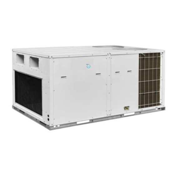
Rooftop Packaged Service Manual PRODUCT PRODUCT INTRODUCTION 1 MODELS LIST Nominal Model Power Capacit Supply Appearance Refrigerant Model Name (V, Ph, Hz) (Ton) 380~415V, CH-IRT05NM R410A 3Ph, 50/60Hz 380~415V, CH-IRT08NM R410A 3Ph, 50/60Hz 380~415V, CH-IRT15NM R410A 3Ph, 50/60Hz Notes: ① Above pictures may be different from actual model. -
Page 6: Nomenclature
Rooftop Packaged Service Manual PRODUCT 2 NOMENCLATURE - Description Options Product Category CH=Cooper&Hunter Compressor Type I = Inverter. Unit Type RT=Rooftop. 05=5Ton; Cooling/Heating Capacity 08=8Ton..Refrigerant Options N=R410a; Voltage Options M=380~415V,50/60Hz,3PH 3 FUNCTION Function Description OPERATING EFFICIENCY All units provide high operating efficiencies and have a minimum EER of 11.0 or above. Grooved copper tubes and enhanced aluminum fin construction improves heat transfer EXCLUSIVE COIL DESIGN for maximum efficiency and durability. -
Page 7: Product Data
Rooftop Packaged Service Manual PRODUCT 4 PRODUCT DATA 4.1 PRODUCT DATA AT RATED CONDITION Nominal Capacity (Ton) CH-IRT05NM CH-IRT08NM CH-IRT15NM Model Name Btu/h 53000 88000 136500 Rated Cooling Capacity 15530 25800 40000 Btu/h 24000~62000 31000~122800 50000~177400 Cooling Capacity Range 7000~18150... -
Page 8: Operation Range
Rooftop Packaged Service Manual PRODUCT kg (lbs) 5(12.98) 16(41.54) 21(54.52) Refrigerant R410A/One R410A/One R410A/One charge Type/Circuit Refrigerant Refrigerant Refrigerant Refrigerant Circuit Circuit Circuit Electronic Electronic Electronic Refrigerant Control expansion valve expansion valve expansion valve inch 68.9×43.3×32.1 83.1×57.1×48.4 110.6×88.2×48.4 Outline 1750×1100×815 2110×1450×1230 2810×2240×1230 Dimensions(... -
Page 9: Electrical Data
Supply Blower Compressor Breaker Min. Power Motors Motor Capacity Supply Cord Model Power Supply Qty. − V/Ph/Hz 380-415, CH-IRT05NM 3.15 3,50/60 380-415, CH-IRT08NM 13.6 3.15 3,50/60 380-415, CH-IRT15NM 20.5 10.0 3,50/60 5 PIPING DIAGRAM (Refrigerant flowing direction is shown as the arrow) - Page 10 Rooftop Packaged Service Manual CONTROL CONTROL...
-
Page 11: Units Control
Rooftop Packaged Service Manual CONTROL UNITS CONTROL 1 OPERATION FLOWCHART 1.1 COOLING OPERATION Power Open unit running at cool mode Indoor fan run Satisfying open Comp. condition Comp. and outdoor fan run Temp of indoor ≤Set temp Comp. and outdoor fan stop Comp. -
Page 12: Heating Operation
Rooftop Packaged Service Manual CONTROL 1.2 HEATING OPERATION... -
Page 13: Wireless Remote Controller
Rooftop Packaged Service Manual CONTROL 2 WIRELESS REMOTE CONTROLLER Notes: The wireless remote controller is an Optional Fitting 2.1 OPERATION AND DISPLAY VIEW Table 2-2-1 Operation instruction of wireless remote controller Name Function Description Signal Signal transmitter transmitter Press this button and the unit will be turned on; press it once more, and the unit will be turned ON/OFF off. - Page 14 Rooftop Packaged Service Manual CONTROL Preset temperature can be decreased by pressing this button. Pressing and holding this button for more than 2 seconds can make the temperature changed quickly until release this button - button and then transmit this order. The temperature adjustment is unavailable un der the Auto mode, but the order can be sent by pressing this button.
- Page 15 Rooftop Packaged Service Manual CONTROL Pressing this button can activate or deactivate the X-FAN function. In Cool or Dry mode, by pressing this button, if " " is displayed, it indicates the X-FAN function is activated. By X-FAN repressing this button, if " "...
-
Page 16: Wired Controller
Rooftop Packaged Service Manual CONTROL 3 WIRED CONTROLLER 3.1 DISPLAY VIEW Figure 2-3-1 Appearance of wired controller Figure 2-3-2 LCD display of wired controller Table 2-3-1 Instruction to LCD Display Icons Introduction Left and right swing function Up and down swing function Air exchange function... - Page 17 Rooftop Packaged Service Manual CONTROL Sleep function Auto mode COOL mode DRY mode FAN mode HEAT mode Health function I-Demand function Vacation function Status display of master and slave wired controller Shield function The button operation, temperature setting, "On/Off" operation, "Mode" setting, and "Save"...
-
Page 18: Operation View
Rooftop Packaged Service Manual CONTROL 3.2 OPERATION VIEW 3.2.1 Silk Screen of Buttons Figure 2-3-3 Silk screen of buttons 3.2.2 Instruction to Function of Buttons Table 2-3-2 Instruction to buttons of wired controller Description Functions ①. Function selection and canceling; ②. - Page 19 Rooftop Packaged Service Manual CONTROL Upon startup of the unit without malfunction or under off state of the unit, press 2 ▲ ▲ and ▼ buttons at the same time for 5s to enter lock state. In this case, any Lock other buttons won‟t respond when pressing.
- Page 20 Rooftop Packaged Service Manual CONTROL Enquiry and setting of wired controller‟s address is shown as Figure 2-3-4 below: Figure 2-3-4 Enquiry and setting of wired controller‟s address 3.2.3.2 Setting of Master/Slave Wired Controller‟s Address Under off status of the unit, press Enter/Cancel and Mode buttons at the same time for 5s to go to the enquiry and setting interface of master/slave wired controller.
-
Page 21: Operation Instructions Of Special Functions
Rooftop Packaged Service Manual CONTROL Figure 2-3-5 Enquiry and setting of master/slave wired controller‟s address 4 OPERATION INSTRUCTIONS OF SPECIAL FUNCTIONS 4.1 SETTING OF FILTER CLEAN REMINDER FUNCTION When unit is on, press Function button to switch to filter clean reminder function. The icon will blink and then enter setting of filter clean reminder function. - Page 22 Rooftop Packaged Service Manual CONTROL Figure 2-4-1 Setting of filter clean reminder function When setting the filter clean reminder function, timer zone will display 2 digits, of which the former indicates the pollution degree of operating place and the latter indicates the accumulated operating time of indoor unit.
-
Page 23: Low Temperature Drying Function
Rooftop Packaged Service Manual CONTROL (4) Heavy pollution: the former digit in timer zone shows 3 while the latter one shows 0, which indicates the accumulated operating time is 100hr. Each time the latter digit increases 1, the accumulated operating time increases 100hr. When it reaches 9, it means the accumulated operating time is 1000hr;... -
Page 24: Memory Function
Rooftop Packaged Service Manual CONTROL When Lock function is turned on, any other buttons won‟t respond when pressing. The function can be memorized after power failure and then power recovery. 4.4 MEMORY FUNCTION Press Mode and ▲ buttons at the same time for 5s under off state of the unit to turn on or cancel memory function. - Page 25 Rooftop Packaged Service Manual CONTROL The address mode is defaulted to be connecting to centralized controller mode and the defaulted address is 1. (3) Setting method: Firstly, set the address mode of wired controller into centralized controller address mode. The setting method is: Under off state of the unit, press Function and Timer buttons at the same time for 5s to go to the debugging menu.
-
Page 26: Switch Between Fahrenheit And Centigrade
Rooftop Packaged Service Manual CONTROL Figure 2-4-4 Note: ① In order to realize the MODBUS interface function, the address mode of the unit must be set into long-distance control address mode; you can not set it into centralized control address mode, otherwise, this function can not be realized;... -
Page 27: Enquiry Of Historical Malfunction
Rooftop Packaged Service Manual CONTROL 20s will also exit enquiry state. Note: ① If the unit is not connected to outdoor ambient temperature sensor, display of outdoor ambient temperature will be shielding after energizing for 12hr. ② If there is malfunction of outdoor ambient temperature sensor, display of outdoor ambient temperature will be shielding after energizing for 12hr. - Page 28 Rooftop Packaged Service Manual CONTROL Under debugging state, press Mode button to adjust to “02” in temperature displaying zone. Timer zone displays setting state and press ▲ or ▼ button to adjust. There are 2 selections: Displayed (LCD displays 01) ...
- Page 29 Rooftop Packaged Service Manual CONTROL Without low-power consumption mode (LCD displays 01) 4.9.8 Selecting door control function Under debugging state, press Mode button to adjust to “08” in temperature displaying zone. Timer zone displays setting state and press ▲ or ▼ button to adjust. There are 2 selections: ...
-
Page 30: Installation Of Wired Controller
Rooftop Packaged Service Manual CONTROL 4.9.12 Selecting compensation of temperature sensor at air return Under debugging state, press Mode button to adjust to “12” in temperature displaying zone. Timer zone displays setting state and press ▲ or ▼ button to adjust. There are 16 selections: ... -
Page 31: Installation Position And Requirement
Rooftop Packaged Service Manual CONTROL Figure 2-5-1 5.2 INSTALLATION POSITION AND REQUIREMENT (1) Prohibit installing the wired controller at the misty place or the place with direct sunlight. (2) Prohibit installing the wired controller at the place near high temperature objects or water-splashing places. -
Page 32: Removal Of Wired Controller
Rooftop Packaged Service Manual CONTROL Figure 2-5-2 Installation of wired controller Brief instructions of installation procedure: Pull out the 2-core signal wire in the installation hole of the wall and then let this wire go through the hole at the back of wired controller‟s base plate. Fix the base plate and installation hole of the wall together with screw M4×25. -
Page 33: Troubleshooting
Rooftop Packaged Service Manual CONTROL 6 TROUBLESHOOTING 6.1 DISPLAY OF ERROR CODE Table 2-6-1 Error Code List 1 Error code Error Remarks Compressor high pressure protection Indoor anti-freeze protection Compressor low pressure protection, refrigerant lack protection and refrigerant colleting mode Compressor high discharge temperature protection Communication error Indoor fan motor error... - Page 34 Rooftop Packaged Service Manual CONTROL Drive reset protection Over-current protection Communication error between main control and drive Drive module sensor error Drive module over temperature protection Zero passage protection AC current protection Drive current error Sensor connecting protection Temperature drift protection Bus low voltage protection Bus high voltage protection Charge loop error...
- Page 35 Rooftop Packaged Service Manual CONTROL Fan power protection Fan Current sensor malfunction The Fan motor in loss of synchronization Malfunction from Fan driving part to main-control communication Overheat protection of Fan radiator Fan radiator sensor malfunction Fan Drive Storage chip malfunction Fan Charge circuit malfunction Fan AC input voltage abnormality Fan drive board environment temperature sensor...
- Page 36 Rooftop Packaged Service Manual INSTALLATION INSTALLATION...
-
Page 37: Installation
Rooftop Packaged Service Manual INSTALLATION INSTALLATION 1 UNITS INSTALL 1.1 INSTALLATION POSITIONS To ensure the unit in proper function, selection of installation location must be in accordance with following principles. (1) Unit shall be installed so that the air discharged by outdoor fan will not return and that sufficient space for repair shall be provided around the unit. - Page 38 Rooftop Packaged Service Manual INSTALLATION (1) When removing the unit, two ropes are needed to hang the unit along the four ways. (2) In order to avoid the extrusion, between the ropes should be add something to protect the unit (e.g. batten).
- Page 39 Rooftop Packaged Service Manual INSTALLATION CH - IRT 08 NM C H -I RT 15 NM...
- Page 40 Rooftop Packaged Service Manual INSTALLATION NOTE: ① The diagram may be different from actual model. The diagram is for pedestal made of concrete. ② The high dimension of the pedestal must be enough to install drainpipe (Refer to DRAIN PIPING WORK) 1.2.4 DUCTWORK The design and installation of air ducts must be in conformity with the relevant local engineering criteria.
-
Page 41: Dimension
Rooftop Packaged Service Manual INSTALLATION 1.3 DIMENSION 1.3.1 DIMENSION OF UNITS C H -I RT 05N M C H -I RT 08N M... - Page 42 Rooftop Packaged Service Manual INSTALLATION C H -I RT 15N M Dimension (mm) 5Ton 815 1750 1100 8Ton 1230 2110 1450 100 1112 15Ton 1245 2810 2240 1872 177 168 1900 168 Note: Above diagrams may be different from actual mode.
- Page 43 Rooftop Packaged Service Manual INSTALLATION 1.3.2 INSTALLATION CLEARANCE DATA Note: Above diagrams may be different from actual mode. CH-IRT05NM Installation Clearances DIMENSION inch (Minimum) 1100 1100 1100...
- Page 44 Rooftop Packaged Service Manual INSTALLATION CH-IRT08NM Note: Above diagrams may be different from actual model. CH-IRT15NM Note: Above diagrams may be different from actual model. CH-IRT08NM CH-IRT15NM Installation Clearances DIMENSION (Minimum) inch 1000 1500 1100 1100 1830...
-
Page 45: Drain Piping Work
Rooftop Packaged Service Manual INSTALLATION 2 DRAIN PIPING WORK 2.1 INSTALLATION PROCEDURE After the unit is installed, it is required to check the level of the whole unit. The unit must be placed horizontally to ensure the unit in proper function. When shipped out from factory, both the condensate outlets are blocked by rubber plug. -
Page 46: Electric Wiring Work
Rooftop Packaged Service Manual INSTALLATION 3 ELECTRIC WIRING WORK 3.1 WIRING PRINCIPLE 3.1.1 Precautions (1) Before connecting lines, read the unit nameplate for message about voltages, circuit ampacity, capacity, and so on. Then carry out line connection according to the schematic diagram. (2) The air-conditioning unit shall have special power supply line which shall be equipped with electricity leakage switch and air switch, so as to deal with overload conditions. - Page 47 Rooftop Packaged Service Manual INSTALLATION Remove the screw from the terminal board. Clamp a round terminal of the peeled wires. Screw cross the circle and fix it on the terminal board. 3.1.3 Electrical connections-supply voltage: (1) Air-conditioning unit with single-phase power supply Remove the Electric Box Cover of the unit.
-
Page 48: Electric Wiring Design
Rooftop Packaged Service Manual INSTALLATION 3.2 ELECTRIC WIRING DESIGN Three Phase (380~415V-3Ph-50/60Hz POWER SUPPLY) C H -I RT 05N M CH-IRT05NM C H -I RT 08N M CH-IRT08NM... - Page 49 Rooftop Packaged Service Manual INSTALLATION C H -I RT 15N M CH-IRT15NM...
- Page 50 Rooftop Packaged Service Manual MAINTENANCE MAINTENANCE...
-
Page 51: Maintenance
Rooftop Packaged Service Manual MAINTENANCE MAINTENANCE 1 MALFUNCTION TABLE 1.1 MAIN CONTROL MALFUNCTION Table 1 Fault Display on Wired Controller Origin of Malfunction Error code malfunction Control description name signal When unit detects the high pressure switch is cut off for 3s successively, high pressure protection will occur. - Page 52 Rooftop Packaged Service Manual MAINTENANCE Origin of Malfunction Error code malfunction Control description name signal If the mainboard does not receive data from the other Communication mainboards, communication malfunction will be reported. If Communication between there is communication abnormity between display board malfunction (wired controller) and the unit, communication malfunction mainboards...
- Page 53 Rooftop Packaged Service Manual MAINTENANCE Origin of Malfunction Error code malfunction Control description name signal If the discharge temperature sensor is detected of open Malfunction of circuit or short circuit for 5s successively after the Discharge discharge compressor has been operating for 3min, discharge temperature temperature sensor malfunction will be reported.
-
Page 54: Description Of Drive Malfunction
Rooftop Packaged Service Manual MAINTENANCE Origin of Malfunction Error code malfunction Control description name signal Communication Communication If the outdoor main control board does not receive data from malfunction between main drive board, communication malfunction between main between main control board control and drive will be reported. - Page 55 Rooftop Packaged Service Manual MAINTENANCE Condenser Fan Missing phase Condenser Fan Drive module resetting Condenser Fan current protection Condenser Fan power protection Condenser Fan Current sensor malfunction Condenser Fan motor in loss of synchronization Malfunction from Condenser Fan driving part to main-control communication Overheat protection of Condenser Fan radiator Condenser Fan radiator sensor malfunction...
-
Page 56: Flow Chart Of Troubleshooting
Rooftop Packaged Service Manual MAINTENANCE 2 FLOW CHART OF TROUBLESHOOTING 2.1 TROUBLESHOOTING FLOW CHART OF MAIN CONTROL MALFUNCTION E1 High Pressure Protection protection Reconnect wire according to the circuit diagram Check if the system high Check if the wiring Check if the high Replace the high pressure is... - Page 57 Rooftop Packaged Service Manual MAINTENANCE (3) Refrigerant recycling mode; 1)If enter refrigerant recycling mode through special operation, the displayed E3 is not an error code. It will be eliminated when exiting refrigerant recycling mode. 2)If you do not want to have refrigerant lacking protection, you can enter the debugging mode through wired controller and then cancel the refrigerant lacking protection mode.
- Page 58 Rooftop Packaged Service Manual MAINTENANCE E4 Discharge Protection E4 protection Replace the discharge temperature sensor Check if the discharge Check if the temperature around discharge Replace the outdoor compressor discharge temperature sensor main control board temperature sensor is normal exceeds 115℃...
- Page 59 Rooftop Packaged Service Manual MAINTENANCE F0 Malfunction of Indoor Ambient Temperature Sensor Malfunction of indoor ambient temperature sensor Check if the indoor ambient temperature Correctly insert the sensor on mainboard is inserted temperature sensor on the needle on the needle stand stand correctly Disconnect Replace the...
- Page 60 Rooftop Packaged Service Manual MAINTENANCE F2 Malfunction of Condenser Temperature Sensor Malfunction of condenser temperature sensor Check if the condenser Correctly insert the temperature sensor on temperature sensor mainboard is inserted on the on the needle stand needle stand correctly Disconnect Replace the the temperature sensor and...
- Page 61 Rooftop Packaged Service Manual MAINTENANCE F4 Malfunction of Discharge Temperature Sensor Malfunction of discharge temperature sensor Check if the Correctly insert the discharge temperature sensor on temperature sensor mainboard is inserted on the on the needle stand needle stand correctly Disconnect Replace the the temperature sensor and...
- Page 62 Rooftop Packaged Service Manual MAINTENANCE F5 Malfunction of Wired Controller Temperature Sensor Malfunction of wired controller temperature sensor Replace the wired controller H6 Malfunction of Outdoor Fan Motor Malfunction of Outdoor Fan Motor Check if the Correctly connect the control wire of outdoor fan motor is control wire of fan motor connected on the outdoor...
-
Page 63: Troubleshooting Flow Chart Of Drive Malfunction
Rooftop Packaged Service Manual MAINTENANCE E8 Malfunction of Indoor Fan Motor Malfunction of indoor fan motor Check if the Correctly connect the control wire of indoor fan motor is control wire of fan motor connected on the outdoor on the mainboard mainboard correctly Replace the indoor fan motor and then... - Page 64 Rooftop Packaged Service Manual MAINTENANCE PH DC busbar over-voltage protection PL DC busbar under-voltage protection PH or PL is displayed on the wired controller PH or PL is displayed in the mainboard 88 indicating lamp Is input voltage ranged from 185VAC to 264VAC? Replace the...
- Page 65 Rooftop Packaged Service Manual MAINTENANCE P6 Drive-to-main-control communication error Lc Compressor Startup Failure Lc is displayed on the wired controller Lc is displayed in the mainboard 88 indicating lamp Replace the mainboard. Does it work normally? Replace the compressor Work normally ...
- Page 66 Rooftop Packaged Service Manual MAINTENANCE ee driving board chip error ee is displayed on the wired controller Replace the mainboard Work Normally H6 DC fan error H6 is displayed on the wired controller H6 is displayed in the mainboard 88 indicating lamp Is the motor phase sequence...
-
Page 67: Wiring Diagram
Rooftop Packaged Service Manual MAINTENANCE 3 WIRING DIAGRAM Model: C H -I RT 05N M X T 1 X1(AC-L1) X2(AC-L2) POWER X3(AC-L3) W14 W15 W16 (AC-L) (L1-F) (N-F) (L2-F) (L3-F) The position of electric components The upper part of electric box Θ... - Page 68 Rooftop Packaged Service Manual MAINTENANCE Model: C H - IRT 15N M POWER W12 W13 EKV1 OVC-COMP HEAT COMM1 T-SENSOR2 CAP(02) JUMP2 CN101 RECTIFIER BRIDGE RECTIFIER BRIDGE CN101 Sketch Map of Electric Parts in Electrical Box1 CN302 CN303 CN302 AP10 AP11 CN303 CN102...
-
Page 69: Disassembly And Assembly Procedure Of Main Parts
Rooftop Packaged Service Manual MAINTENANCE 4 DISASSEMBLY AND ASSEMBLY PROCEDURE OF MAIN PARTS 4.1 Model: CH-IRT05NM Disassembly and Assembly of Compressor Remark: Make sure there isn't any refrigerant in pipe system and the power supply is cut off before removal of the compressor. - Page 70 Rooftop Packaged Service Manual MAINTENANCE Heat the connection pipes indicated 4. Cut off the by arrows with fired heater and then connection between draw out them. compressor and Note: Pay attention to things around to pipes. avoid burning out. ...
- Page 71 Rooftop Packaged Service Manual MAINTENANCE Reconnect the power cord into compressor according to the procedure of disconnecting power cord. The line connection must 8. Reconnect power accord to the schematic diagram. cord of compressor. Note: The connection box of compressor must be re-covered to resisting water.
- Page 72 Rooftop Packaged Service Manual MAINTENANCE Disassembly and Assembly of Condenser Fan Motor Remark: Make sure that the unit is stopped running and power supply is cut off before removal of the motor. Step Illustration Handling Instruction Disconnect all connection lines between motor and elements in electric box.
- Page 73 Rooftop Packaged Service Manual MAINTENANCE Put the repaired or replaced motor onto brakcet as the direction during removing. Then 5. Fix the new screw down the holding motor on to the bolt with a wrench. bracket. Note: Please keep the motor level and vertical during installation.
- Page 74 Rooftop Packaged Service Manual MAINTENANCE Disassembly and Assembly of Supply Blower Motor Remark: Make sure that the unit is stopped running and power supply is cut off before removal of the motor. Step Illustration Handling Instruction Unscrew the screws fixing cover plate .Lift the 1.
- Page 75 Rooftop Packaged Service Manual MAINTENANCE 4. Remove the fan Remove the fan volute. volute. 5. Remove the fan Remove the fan blade. blade 6. Install the fan Install the fan blade blade. 7. Install the fan Install the fan volute. volute.
- Page 76 Rooftop Packaged Service Manual MAINTENANCE Re-insatll the whole fan 8. Re-install fan sub-assy and then fix the sub-assy. screws indicated by arrows. Re-connect power cord according to wiring diagram adhered on eletric box. Note: After connection, 9. Re-connect arrange leading wires and power cord.
- Page 77 Rooftop Packaged Service Manual MAINTENANCE NOTE: Above diagrams may be different from actual model. Disassembly and Assembly of Electric Box Remark: Make sure that the unit is stopped running and power supply is cut off before removal . Step Illustration Handling Instruction ...
- Page 78 Rooftop Packaged Service Manual MAINTENANCE Unscrew the screws (indicated by the arrows),and then take 5. Take down the down the electric box. electric box. Note: Power cord may be fixed by bundles, so loose the bundles before taking out the electric box.
- Page 79 Rooftop Packaged Service Manual MAINTENANCE Put the side plate back 9. Re-install the side plate. and tighten the screws. NOTE: Above diagrams may be different from actual model.
-
Page 80: Model: Ch-Irt08Nm
Rooftop Packaged Service Manual MAINTENANCE 4.2 Model: CH-IRT08NM Model: C H -I RT 08N M Disassembly and Assembly of Compressor Remark: Make sure there isn't any refrigerant in pipe system and the power supply is cut off before removal of the compressor. - Page 81 Rooftop Packaged Service Manual MAINTENANCE Unscrew the nuts on compressor 5. Take down the base with a wrench and then remove compressor from the compressor from the base. base. Note: Keep compressor level and vertically out. Never invert it. ...
- Page 82 Rooftop Packaged Service Manual MAINTENANCE Put the cover plate back and tighten 9. Re-install the cover plate. the screws. Connect refrigerant tank with nozzle of low pressure (indicated by the 10. Recharge maker) for recharging refrigerant. refrigerant. Note: Check the leak after finishing the connectionpipes.
- Page 83 Rooftop Packaged Service Manual MAINTENANCE Unscrew the screws 2. Take out the fixing cover plate cover plate. (indicated by arrows) to take it out. Unscrew the screw (indcated by the arrow) fixing fan to take the fan out. 3.
- Page 84 Rooftop Packaged Service Manual MAINTENANCE Put the repaired or replaced motor onto brakcet as the direction during removing. Then screw down the 5. Fix the new holding bolt with a motor on to the wrench. bracket. Note: Please keep the motor level and vertical during installation.
- Page 85 Rooftop Packaged Service Manual MAINTENANCE locations. Close the cover plate of electric box hermetically. All cable can not contact the pipe and moving parts such as fan. NOTE: Above diagrams may be different from actual model. Disassembly and Assembly of Supply Blower Motor Remark: Make sure that the unit is stopped running and power supply is cut off before removal of the motor.
- Page 86 Rooftop Packaged Service Manual MAINTENANCE Unscrew holding bolt(indicated by the 3. Take down the arrow) of fan sub-assembly sub-assembly . bracket with a wrench Unscrew the screws 4. Remove the screws on fan fixing cover plate sub-assembly. (indicated by arrows) ...
- Page 87 Rooftop Packaged Service Manual MAINTENANCE Re-assemble repaired or replaced 6. Install the fan motor and the fan. and motor Installation direction is the same as that during disassembly. Then screw down the 7. Fix the fan sub-assembly on holding bolt with a to the bracket.
- Page 88 Rooftop Packaged Service Manual MAINTENANCE Put the cover plate 9. Re-install the back and tighten the cover plate screws. NOTE: Above diagrams may be different from actual model. Disassembly and Assembly of Electric Box Remark: Make sure that the unit is stopped running and power supply is cut off before removal . Step Illustration Handling Instruction...
- Page 89 Rooftop Packaged Service Manual MAINTENANCE Unscrew the screws 3. Take out the fixing cover (indicated electric box by the arrows).Then cover. take out the cover. Disconnect all connection lines between exterior electric component and elements in 4. Disconnect electric box.
- Page 90 Rooftop Packaged Service Manual MAINTENANCE Put the electric box back and tighten the screws. Then reconnect all connection lines that had been take down, and refix the Power 6. Re-install the cord with bundles at electric box. original locations. Note: The line connection must accord to the schematic...
-
Page 91: Model: C H -I Rt 15N M
Rooftop Packaged Service Manual MAINTENANCE Put the side plate 9. Re-install the back and tighten the side plate. screws. NOTE: Above diagrams may be different from actual model. 4.3 Model: CH-IRT15NM Disassembly and Assembly of Compressor Remark: Make sure there isn't any refrigerant in pipe system and the power supply is cut off before removal of the compressor. - Page 92 Rooftop Packaged Service Manual MAINTENANCE Heat the connection pipes indicated 4. Cut off the by arrows with fired heater and then connection between draw out them. compressor and Note: Pay attention to things around to pipes. avoid burning out. ...
- Page 93 Rooftop Packaged Service Manual MAINTENANCE Reconnect the power cord into compressor according to the procedure of disconnecting power cord. The line connection must 8. Reconnect power accord to the schematic diagram. cord of compressor. Note: The connection box of compressor must be re-covered to resisting water.
- Page 94 Rooftop Packaged Service Manual MAINTENANCE Unscrew the screws fixing cover 2. Take out the cover plate (indicated by arrows) to take it plate. out. Unscrew the screw (indcated by the arrow) fixing fan to take the fan out. 3.
- Page 95 Rooftop Packaged Service Manual MAINTENANCE Put the cover plate back and tighten 7. Re-install the cover plate. the screws. Re-connect power cord according to circuit mark adhered on eletric box. Note: After connection, arrange leading 8. Re-connect power wires and refix them with bundles at cord.
- Page 96 Rooftop Packaged Service Manual MAINTENANCE 3. Remove the Unscrew the screws fixing cover screws on fan plate (indicated by arrows) sub-assembly. 4.Remove the fan Remove the fan blade and blade and Propeller Propeller Housing Housing Unscrew the holding screw of fan (indicated by the arrows) to loose connection between motor shaft 5.
- Page 97 Rooftop Packaged Service Manual MAINTENANCE Re-assemble repaired or replaced motor and brakcet. Installation 7. Fix the motor on to direction is the same as that during the bracket. disassembly. Then screw down the holding bolt with a wrench. 8. Install the fan Install the fan blade and Propeller blade and Propeller Housing...
- Page 98 Rooftop Packaged Service Manual MAINTENANCE Re-connect power cord according to wiring diagram adhered on eletric box. Note: After connection, arrange 11. Re-connect leading wires and refix them with power cord. bundles at original locations. All cable can not contact the pipe and moving parts such as fan.
- Page 99 Rooftop Packaged Service Manual MAINTENANCE Disassembly and Assembly of Electric Box Remark: Make sure that the unit is stopped running and power supply is cut off before removal . Step Illustration Handling Instruction Pull out power cord or disconnect the power cord after unscrewing the screws.
- Page 100 Rooftop Packaged Service Manual MAINTENANCE Put the electric box back and tighten the screws. Then reconnect all connection lines that had been take down, and 5. Re-install the refix the Power cord with electric box. bundles at original locations. Note: The line connection must accord to the schematic diagram.
-
Page 101: Exploded Views And Spare Part List
Rooftop Packaged Service Manual MAINTENANCE 5 EXPLODED VIEWS AND SPARE PART LIST ◆ Model: C H -I RT 05N M... - Page 102 Rooftop Packaged Service Manual MAINTENANCE C H -I RT 05N M Name of Part Part Code Quantity Top Cover Board Sub-Assy 1 '017011000004 Air Duct Sub-Assy '017107000007P Centrifugal Fan '10425200002 Brushless DC Motor '15704100009 Propeller Housing(Upper) '26905200010 Propeller Housing(Lower) '26905200011 Evaporator Assy '011001000085 Clapboard Sub-Assy 1(Middle)
- Page 103 Rooftop Packaged Service Manual MAINTENANCE Compressor and Fittings '00103923_G Gas-liquid Separator '07423902 Pressure Switch '4602001531 Pressure Protect Switch '4602000910 4-way Valve '43000338 Chassis Sub-Assy 2 '017000000067P Rear Grill 1 '016001000005 Brushless DC Motor '15704124 Magnet Coil '4300040032 Reactor '43130192 Rear Grill 3 '016001000003 Side Plate(Left) '017110000003...
- Page 104 Rooftop Packaged Service Manual MAINTENANCE ◆ Model: C H -I RT 08N M C H -I RT 08N M Name of Part Quantity Part Code Top Cover Sub-Assy 1 '30294000007 Temperature Sensor '01573702P Temperature Sensor '01523901P Temperature Sensor '012049000010P Discharge Sensor '10434100002 Air Flue Assy '15704124...
- Page 105 Rooftop Packaged Service Manual MAINTENANCE Brushless DC Motor '016001000009 Blower(Right) '4304000425 Filter Sub-Assy '4304000430 Evaporator Assy '43000054 Bidirection Strainer '00204100003 Electric Box Assy '06130002 Radiator 2 '76710247 Radiator 1 '4304413214 Main Board '4304413220 Rectifier '43044100190 Electric Box Assy '04324001 Radiator '4602001535 Radiator '4304000402...
- Page 106 Rooftop Packaged Service Manual MAINTENANCE One way Valve '30221000023 Pressure Protect Switch '420101852 Strainer '42011051 Electromagnetic Valve '300002000147 Magnet Coil '49018000001 Pressure Switch '49018000068 One way Valve '100002000253 Electronic Expansion Valve '46010604 Electric Expand Valve Fitting '30223000034 „430034000022 Electric Expand Valve Fitting „430034000021 Compressor Gasket Nozzle for Adding Freon...
- Page 107 Rooftop Packaged Service Manual MAINTENANCE ◆ Model: C H -I RT 15N M C H -I RT 15N M Name of Part Part Code Quantity Top Cover Board Sub-Assy 3 '017011000007 Diversion Circle '012193000001P ‟15704100011 Brushless DC Motor Axial Flow Fan '10434100007 Brushless DC Motor '15704100011...
- Page 108 Rooftop Packaged Service Manual MAINTENANCE Brushless DC Motor '1570410000901 Centrifugal Fan Assy '000052000027 Evaporator Assy '011001000351 Magnet Coil (Electromagnetic Valve) '4304000473 Electric Expand Valve Fitting '4304413207 Electromagnetic Valve '43000072 Electronic Expansion Valve '43044100190 One Way Valve '04324001 Strainer '07415200002 Bidirection Strainer '07210044 Radiator 2 '430034000021...
- Page 109 Rooftop Packaged Service Manual MAINTENANCE Electric Expand Valve Fitting '4304413227 Nozzle for Adding Freon '06130002 Electrical Heater(Compressor) '7651521217 Oil Separator '0742418601 Chassis Sub-Assy 3 '017000000098P Pressure Protect Switch '4602000910 Pressure Protect Switch '4602000912 Pressure Protect Switch '46020015106 Magnet Coil '4304000401 Electromagnetic Valve '43003091 Magnet Coil...
- Page 110 Cooper&Hunter International Corporation www.cooperandhunter.com...
Need help?
Do you have a question about the CH-IRT05NM and is the answer not in the manual?
Questions and answers