Table of Contents
Advertisement
Available languages
Available languages
Quick Links
Advertisement
Chapters
Table of Contents

Related Manuals for Ferroli VARESE Series


Summary of Contents for Ferroli VARESE Series
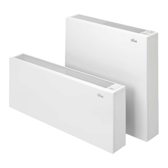
- Page 1 VARESE RADIADOR DE BAJA TEMPERATURA LOW TEMPERATURE RADIATOR RADIATORE A BASSA TEMPERATURA Mod. MOD. VARESE VARESE LP VARESE HE VARESE LP HE VARESE LP VARESE HE MANUAL TÉCNICO Y DE INSTALACIÓN TECHNICAL AND INSTALLATION MANUAL MANUALE TECNICO E D’INSTALLAZIONE...
- Page 2 Estimado cliente: Muchas gracias por elegir un producto FERROLI. Este equipo es el resultado de largos años de experiencia y estudios de diseño, y ha sido fabricado con materiales de primera calidad y tecnología avanzada. El marcado CE garantiza que los equipos cumplen todas las directivas europeas aplicables.
-
Page 4: Table Of Contents
ÍNDICE Características generales ......................... Finalidad de la máquina ........................ Componentes principales ......................Tipos de instalación admitidos ...................... Tablas de características técnicas ....................10 Dimensiones ..........................11 Posición de las tomas hidráulicas ....................11 Instalación de la unidad ..........................12 Instalaciones monotubo ........................ 12 Instalaciones bitubo ........................ - Page 5 IMPORTANTE - Si el cable de alimentación está deteriorado, debe cambiarse por el fabricante, su servicio posventa o las personas cualifi cadas para ello, con objeto de evitar un posible peligro. - Se debe proteger la línea eléctrica con un dispositivo diferencial de alta sensibilidad - El radiador debe instalarse de tal modo que alrededor del emisor térmico haya el sufi...
-
Page 6: Características Generales
CARACTERÍSTICAS GENERALES FINALIDAD DE LA MAQUINA VARESE LP HE Los emisores VARESE son radiadores de alto rendimiento indicados para instalaciones de calefacción a baja temperatura, con muy bajo contenido en agua y versátiles en las instalaciones 1.1 VERSIONES DISPONIBLES VARESE Emisor para baja temperatura con kit HE, ventiladores brushless y sondas de control de temperatura y panel táctil. -
Page 7: Tipos De Instalación Admitidos
CARACTERÍSTICAS GENERALES TIPO DE INSTALACIONES ADMITIDOS 6. Sonda de temperatura de entrada de agua 7. Conexiones hidráulicas: tomas de entrada y salida de agua de tipo hembra de ½” para agua, con purgadores gemelos y Los emisores VARESE son aptos para instalaciones de calefacción simétricos. - Page 8 CARACTERÍSTICAS GENERALES INSTALACIONES BITUBO - OBRA NUEVA 1. Salida de pared 2. Tubería de unión con toma superior (a cargo del instalador) 3. Toma superior-entrada de agua (racor a cargo del instalador) 4. Cabezal termostático (a cargo del instalador) 5. Toma inferior-retorno de agua. Entrada a pared (racor a cargo del instalador).
- Page 9 CARACTERÍSTICAS GENERALES 1. Salida de pared 3.3. 3 Entrada inferior, retorno inferior en el lado contrario. 2. Tubería de unión con toma superior (a cargo del instalador) 3. Toma superior-entrada de agua (racor a cargo del instalador) 4. Cabezal termostático (a cargo del instalador) 5.
-
Page 10: Tablas De Características Técnicas
CARACTERÍSTICAS GENERALES TABLA DE CARACTERÍSTICAS: MODELOS HE 1000 LP 500 LP 600 LP 800 LP 1000 MODELO Modo Eco 1138 369.8 576.5 1050.3 Potencia Calorífica Modo Confort 498.6 1228.6 401.1 617.5 915.6 1131.6 55/45/20 C* Modo Boost 569.6 767.2 1112.6 1517 1087.6 1493.3... -
Page 11: Dimensiones
CARACTERÍSTICAS GENERALES DIMENSIONES POSICIÓN DE LAS TOMAS HIDRÁULICAS - Tomas de 1/2” hembra - 75mm desde la pared - Reversibles - Entrada de agua siempre por la toma superior Modelo 1000 1000 A (mm) 1094 1094 Peso (Kg) 10.6 1000 Modelo 1000 A (mm) -
Page 12: Instalación De La Unidad
INSTALACIÓN DE LA UNIDAD INSTALACIONES MONOTUBO Coloque la carcasa exterior en los agujeros. Elimine las sujecciones para el transporte del intercambiador térmico, así como los tapones de las tomas superior e inferior del emisor. Retire así mismo los tapones de goma de protección del intercambiador térmico. -
Page 13: Instalaciones Bitubo
INSTALACIÓN DE LA UNIDAD Ensamble el panel frontal. En los modelos con sistema Con ayuda de la plantilla provista en la parte posterior HE, coloque de nuevo los tapones embellecedores en los del embalaje, marque en la pared los puntos de anclaje (2 agujeros frontales. -
Page 14: Conexión Del Sistema He
INSTALACIÓN DE LA UNIDAD CONEXION DEL SISTEMA HE Con ayuda de un pequeño martillo de goma, abra el agujero pretaladrado de la carcasa necesario para dejar accesible el cabezal termostático. Los modelos equipados con el sistema HE vienen preinstalados para tomas de agua en el lado derecho. Si su instalación requiere de tomas en el lado izquierdo, siga los siguientes puntos en orden. -
Page 15: Operación
OPERACIÓN 5. Conecte el cable de alimentación del KIT HE de ventiladores. Este sistema está preparado para funcionar de forma totalmente autónoma y desatendida desde la primera conexión. Mediante la sonda de entrada de agua, el sistema se pone en marcha y se para automáticamente cuando la caldera o el grupo térmico se ponga en marcha o se detenga. -
Page 16: Limpieza Y Mantenimiento
STAND-BY parpadeando rápido: error en la sonda de ambiente. Modo AUTO y Stand By parpadeando: error en ambas sondas. En caso de aparecer alguno de estos errores, póngase en contacto con el Servicio Técnico de Ferroli. cod. A73022041... - Page 17 INDEX General characteristics ........................19 Purpose of device ........................19 Main components ........................19 Types of installation supported ....................20 Technical specifications table ....................23 Dimensions ..........................24 Position of hydraulic connection ....................24 Unit installation............................25 One-pipe systems ........................25 Two-pipe systems.........................
- Page 18 IMPORTANT - If the power cable is damaged, it must be replaced by the manufacturer, its after-sales service or the qualifi ed persons, in order to avoid a possible danger. - The power line must be protected with a high sensitivity differential device - The radiator must be installed in such a way that around the thermal emitter there is enough space for proper circulation of...
- Page 19 GENERAL CHARACTERISTICS PURPOSE OF DEVICE VARESE LP HE The VARESE emitters are high performance radiators suitable for heating at low temperature, with very low water content and straightforward installation. 1.1 VERSIONS AVAILABLE VARESE Low temperature emitter with HE kit, brushless fans, temperature control sensors and touch panel.
- Page 20 GENERAL CHARACTERISTICS TYPES OF INSTALLATION SUPPORTED 5. Room temperature sensor: NTC probe for measuring the ambient temperature of the room. 6. Water inlet temperature sensor The VARESE emitters are suitable for one-pipe and two-pipe 7. Hydraulic connections: ½ female type water inlet and outlet heating installations, in new constructions or the replacement of sockets with twin and symmetrical type steam bleeders.
- Page 21 GENERAL CHARACTERISTICS TWO-TUBE INSTALLATION NEW CONSTRUCTION 1. Wall outlet 2. Connecting piping with upper connection socket (by the installer) . 3. Upper water inlet connection socket (fitting by the installer) . 4. Electro thermostatic valves (by the installer) . 5. Lower water outlet socket Wall inlet (fitting by the installer). 3.3.
- Page 22 GENERAL CHARACTERISTICS 1. Wall outlet 3.3. 3 Upper inlet, lower outlet on the opposite side. 2. Connecting piping with upper socket (by the installer) . 3. Upper water inlet socket (fitting by the installer) . 4. Electro thermostatic valves (by the installer) . 5.
- Page 23 GENERAL CHARACTERISTICS TABLE OF VARESE HE MODEL SPECIFICATIONS 1000 LP 500 LP 600 LP 800 LP 1000 MODEL Eco Mode 1138 369.8 576.5 1050.3 Heat output Comfort 498.6 1228.6 401.1 617.5 915.6 1131.6 55/45/20 ºC* Mode Boost Mode 569.6 767.2 1112.6 1517 1087.6...
- Page 24 GENERAL CHARACTERISTICS DIMENSIONS POSITION OF HYDRAULIC CONNECTIONS • 1/2” female socket connections • 75 mm from the wall • Reversible • Water intake always through higher inlet Model 1000 A (mm) 1094 Weight 10.6 (Kg) Model 1000 1000 A (mm) 545 545 1094 1094 Weight...
- Page 25 UNIT INSTALLATION ONE - PIPE SYSTEMS Place the outer over onto the holes emove the clamps for transporting the heat exchanger as well as the plugs from top and bottom emitter sockets. Also remove the rubber plugs heat exchanger. CAUTION : The battery is supplied at a pressure of 1.5 bar pressure with nitrogen to ensure no leakage .
- Page 26 UNIT INSTALLATION Assemble the front panel. On models with HE system, Using the template provided on the back of the package, replace the cover plugs in the front holes. mark on the wall the anchoring points (2 locations) for the heat exchanger, taking into account the position of the water inlets (right or left).
- Page 27 UNIT INSTALLATION HE SYSTEM CONNECTION Using a small rubber hammer, open the pre-drilled hole in the cover enough to make the electro thermostatic valve accessible. Models equipped with the HE system come pre-installed for the wa- ter inlet sockets on the right-hand side. If your installation requires inlet sockets on the left side, follow these points by order.
- Page 28 OPERATION 5. Connect the HE KIT fan power cord. This system is designed to operate completely autonomously and unattended from the first connection. Through the water inlet sensor, the system starts and stops automatically when the boiler or heat group is started or stopped.
- Page 29 AUTO mode blinking: error in the water detection sensor. STAND-BY rapid blinking: error in the ambient sensor. AUTO mode and Stand By blinking: error in both sensors. If any oaf these arroros occur, contact Ferroli Technical Service. cod. A73022041...
- Page 30 INDICE Descrizione dell’apparecchio ....................... 32 Finalità dell’apparecchio ......................32 Componenti principali........................ 32 Tipi consentiti di installazione ....................33 Tabella delle specifiche tecniche ....................36 Dimensioni ..........................37 Posizione delle prese idrauliche ....................37 Installazione dell’apparecchio ......................38 Impianti monotubo........................38 Impianti bitubo ...........................
- Page 31 IMPORTANTE - Qualora il cavo di alimentazione sia danneggiato, è necessario cambiarlo rivolgendosi al fabbricante, al servizio post-vendita o al personale tecnico specializzato, evitando in questo modo un eventuale pericolo. - È necessario proteggere l’impianto elettrico mediante un interruttore differenziale ad alta sensibilità. - Il radiatore deve essere installato in modo tale da lasciare uno spazio suffi...
-
Page 32: Descrizione Dell'apparecchio
DESCRIPZIONE DELL’APPARECCHIO F INALITÀ DELL’APPARECCHIO VARESE LP HE Gli emettitori VARESE sono radiatori ad alto rendimento indicati per gli impianti di riscaldamento a bassa temperatura, a basso contenuto di acqua ed estremamente versatili nell’installazione. 1.1 VERSION DISPONIBILI VARESE Emettitore per impieghi a basse temperature con kit HE, ventole brushless, sonda di controllo della temperatura e touchpad di controllo. -
Page 33: Tipi Consentiti Di Installazione
DESCRIPZIONE DELL’APPARECCHIO 5. Sonda di temperatura ambiente: sonda di tipo ntc per misurare TIPI CONSENTITI DI INSTALLAZIONE la temperatura ambiente della sala. 6. Sonda di temperatura di ingresso dell’acqua. 7. Raccordi idraulici: prese di ingresso e uscita dell’acqua di tipo Gli emettitori VARESE sono adatti per impianti di riscaldamento femmina da ½”... - Page 34 DESCRIPZIONE DELL’APPARECCHIO IMPIANTI BITUBO-COSTRUZIONE NUOVA 1. Uscita dalla parete. 2. Raccordi con attacco superiore (a carico dell’installatore). 3. Attacco superiore-ingresso dell’acqua (raccordo a carico dell’installatore). 4. Testina termostatica (a carico dell’installatore). 5. Attacco inferiore-ritorno dell’acqua. Ingresso dalla parete (raccordo a carico dell’installatore). 3.3.
- Page 35 DESCRIPZIONE DELL’APPARECCHIO 3.3. 3 Ingresso inferiore, ritorno inferiore sul lato opposto. 1. Uscita dalla parete 2. Raccordi con attacco superiore (a carico dell’installatore) 3. Attacco superiore-ingresso dell’acqua (raccordo a carico dell’installatore) 4. Testina termostatica (a carico dell’installatore) 5. Attacco inferiore-ritorno dell’acqua. Ingresso dalla parete (raccordo a carico dell’installatore) 6.
-
Page 36: Tabella Delle Specifiche Tecniche
DESCRIPZIONE DELL’APPARECCHIO TABELLA DELLE SPECIFICHE TECNICHE-MODELLI 1000 MODELLO 1000 1138 369.8 576.5 1050.3 Modalitá Eco Potenza Termica 498.6 1228.6 401.1 617.5 915.6 1131.6 Modalitá Comfort 55/45/20 ºC* 569.6 767.2 1112.6 1517 1087.6 1493.3 Modalitá Boost 1067.4 1402.3 1981.4 2637.2 997.7 1325.6 1855.8 2581.4... -
Page 37: Dimensioni
DESCRIPZIONE DELL’APPARECCHIO DIMENSIONI POSIZIONI DELLE PRESE IDRULICHE • Prese da 1/2” femmina • 75mm dalla parete • Reversibili • Ingresso dell’acqua sempre dall’attacco superiore Model 1000 1000 A (mm) 1094 1094 Weight 10.6 (Kg) Model 500 500 1000 1000 A (mm) 545 545 654 1094 1094 Weight... -
Page 38: Installazione Dell'apparecchio
INSTALLAZIONE DELL’APPARECCHIO IMPIANTI MONOTUBO • Collocare il corpo esterno nei fori. • • Eliminare gli elementi di fissaggio per il trasporto dello scam- biatore di calore e i tappi degli attacchi superiori e inferiori dell’emettitore. • Rimuovere anche i tappi in gomma di protezione dello scam- biatore di calore. -
Page 39: Impianti Bitubo
INSTALLAZIONE DELL’APPARECCHIO • Montare il pannello anteriore. Nei modelli con sistema HE, • Segnare sul muro i punti di fissaggio (2 elementi di fissaggio) collocare di nuovo i tappi di protezione nei fori anteriori. della batteria seguendo lo schema presente nella parte poste- riore dell’imballaggio, tenendo presente la posizione delle prese d’acqua (destra o sinistra). -
Page 40: Collegamento Del Sistema He
INSTALLAZIONE DELL’APPARECCHIO COLLEGAMENTO DEL SISTEMA HE • Utilizzare un piccolo martello in gomma per aprire il foro del corpo predisposto necessario per rendere accessibile la testina termostatica. I modelli dotati del sistema HE sono predisposti per le prese d’acqua • sul lato destro. -
Page 41: Operazione
OPERAZIONE 5. Collegare il cavo di alimentazione del KIT HE delle ventole Questo sistema è predisposto per un funzionamento completamente autonomo sin dal primo attacco. Il sistema si mette in moto mediante la sonda di ingresso dell’acqua e si arresta automaticamente nel momento in cui la caldaia o il gruppo termico si accendono o si spengono. -
Page 42: Lavaggio E Manutenzione
Lampeggio veloce STAND-BY: errore nella sonda di ambiente. Lampeggio modalità AUTO e Stand By: errore in entrambe le sonde. In presenza di uno di questi errori, si prega di contattare il Servizio Tecni- co di Ferroli. cod. A73022041... - Page 43 También será necesario, presentar al personal técnico de FERROLI, antes de su intervención, la factura o ticket de compra del aparato junto al albarán de entrega correspondiente, si este fuese de fecha posterior. Las posibles reclamaciones deberán de efectuarse ante el organismo competente en esta materia.
- Page 44 24 mesi dalla data di acquisto. Ferroli S.p.A., pur non essendo venditore finale nei confronti del consumatore, intende comunque supportare le responsabilità del venditore finale con una propria Garanzia Convenzionale, fornita tramite la propria Rete di Assistenza Tecnica Autorizzata alle condizioni riportate di seguito.
- Page 45 Le condizioni di garanzia convenzionale qui elencate sono le uniche offerte da Ferroli Spa. Nessun terzo è autorizzato a modificare i termini della presente garanzia né a rilasciarne altri verbali o scritti.
- Page 46 NOTAS...
- Page 47 NOTAS...
- Page 48 Férroli España S.L.U. - 09007 Burgos (España) - C/. Alcalde Martín Cobos Nº4 Tlf: 947 483250 - Fax: 947 474195 - www.ferroli.es HECHO EN ESPAÑA - MADE IN SPAIN - FABRICATTO IN SPAGNA...
Need help?
Do you have a question about the VARESE Series and is the answer not in the manual?
Questions and answers