Advertisement
Quick Links
Advertisement

Related Manuals for Furukawa OFS DGOI-C 64

Summary of Contents for Furukawa OFS DGOI-C 64
- Page 1 DGOI-C 64 ASSEMBLY INSTRUCTIONS C16AK0001, Issue 1 1/25/2016 Page | 1...
-
Page 2: Table Of Contents
DGOI-C 64 ASSEMBLY INSTRUCTIONS C16AK0001, Issue 1 Contents General Information ..........................3 Composition ............................4 Installation Instruction and Assembly ....................5 Care and Security ..........................23 Discard ..............................23 Technical Assistance ........................... 23 1/25/2016 Page | 2... -
Page 3: General Information
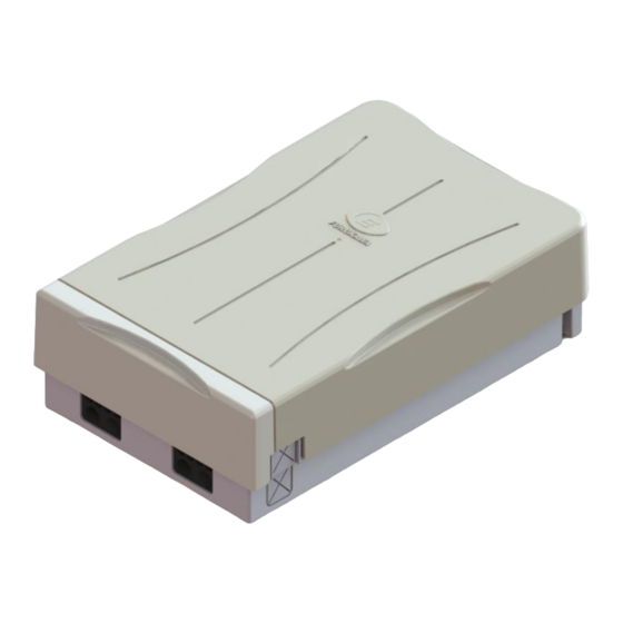
DGOI-C 64 ASSEMBLY INSTRUCTIONS C16AK0001, Issue 1 1. General Information 1.1. Product Description The enclosure is used in optical MDU networks at the building entrance or as a combiner on individual floors in the building, or as a drop cable distribution point for vertical wiring. The enclosure is compatible with connectorized splitters, fan-outs and accepts 64 adapters. -
Page 4: Composition
DGOI-C 64 ASSEMBLY INSTRUCTIONS C16AK0001, Issue 1 2. Composition It is comprised of the components shown in Figure 2 and listed in the Table 1. Fig. 2 Table 1 – List of components in the basic module Description Quantity Cover Base Connection Cover and Base Adapter Tray... -
Page 5: Installation Instruction And Assembly
DGOI-C 64 ASSEMBLY INSTRUCTIONS C16AK0001, Issue 1 Installation Accessories: ● Installation Manual ● M3.5X19 mm long steel, white galvanized, Pan Head Combo Tapping Screw. Qty.4 ● 4 nylon wall anchors S5 (5 x 25) ● 2 Cable Glands (PG 13.5) ●... - Page 6 DGOI-C 64 ASSEMBLY INSTRUCTIONS C16AK0001, Issue 1 Remove the base cover by depressing the locking tab (Fig.4, vertical red arrow) Push the plastic insert and remove the adapter plate (Fig.4); Unscrew the connecting rod from the base and the cover (Fig. 5); Fig.5 NOTE: Select a drill with suitable diameter for anchor wall installation.
- Page 7 DGOI-C 64 ASSEMBLY INSTRUCTIONS C16AK0001, Issue 1 Drill holes at least 25 mm deep in order to insert the provided nylon wall anchors. Secure the base to the wall. The distance between mounting holes is shown on Figure 6. Fig. 6 3.3.
- Page 8 DGOI-C 64 ASSEMBLY INSTRUCTIONS C16AK0001, Issue 1 Install the two enclosures to the wall. Use the following distances for drilling when installing two or more enclosures (Fig. 8). Fig. 8 After attachment of the modules to the wall, insert the plastic expansion bracket (see Fig. Fig.
- Page 9 DGOI-C 64 ASSEMBLY INSTRUCTIONS C16AK0001, Issue 1 Fig. 10 Screw the plastic expansion bracket with two M3X6 mm screws (Fig. 11) Fig. 11 3.4. Adapter Installation Install adapters. Fill the adapter plate from left to right and top to bottom (Fig. 12). Fig.
- Page 10 DGOI-C 64 ASSEMBLY INSTRUCTIONS C16AK0001, Issue 1 3.5. Input Cables Installation Fig. 13 Open 2.5 m of the cable and reserve fiber unit(s) to accommodate the fibers within the enclosure Insert the cable in the rubber cable entry port. When preparing the cable leave 60 mm of strength member (FRP – Strength member) for anchoring the cable Insert the strength member in the position and tighten the bracket screw to secure the cable (Fig.
- Page 11 DGOI-C 64 ASSEMBLY INSTRUCTIONS C16AK0001, Issue 1 3.6. Fiber unit routing to the splice tray Rotate the plastic holders and position the cable as indicated below in Fig. 15 Fig. 15 Route the fibers and prepare the ends for splicing (Fig. 16) Fig.
- Page 12 DGOI-C 64 ASSEMBLY INSTRUCTIONS C16AK0001, Issue 1 Remove the splice tray cover (Fig. 17) Fig. 17 Place the fiber unit into the desired position for installation. Place a mark where to prep the tube/jacket of the cable. (Fig. 18) Fig. 18 1/25/2016 Page | 12...
- Page 13 DGOI-C 64 ASSEMBLY INSTRUCTIONS C16AK0001, Issue 1 Open the jacket or tube and clean the fibers (Fig. 19) Fig.19 Secure the fiber unit in the tray. Cut approximately 10 mm of the foam supplied with the splice tray. Place the fiber unit (either tube or buffered fiber) in the location highlighted in Fig.20; and place the previously cut foam on top.
- Page 14 DGOI-C 64 ASSEMBLY INSTRUCTIONS C16AK0001, Issue 1 Use a cable tie to secure the fiber unit (Fig. 21). Rotate the splice tray to facilitate the plastic cable tie installation Fig. 21 Route the fibers in the tray and cut off the tie-wrap excess (Fig.22) Fig.
- Page 15 DGOI-C 64 ASSEMBLY INSTRUCTIONS C16AK0001, Issue 1 Install the splitter into the holder (Fig. 24) and screw the parking holder in place to support the splitters Fig. 24 Screw the splitters parking support and route the fiber to the tray (Fig.25) Fig.
- Page 16 DGOI-C 64 ASSEMBLY INSTRUCTIONS C16AK0001, Issue 1 Attach the fibers with Velcro. Route the fiber units following the path shown in Figure 27. Plug the connectors to the parking holder as shown. Fig. 27 Fiber units routing 3.8. Pigtail Installation Install the splice trays as needed (Fig.28) Fig.
- Page 17 DGOI-C 64 ASSEMBLY INSTRUCTIONS C16AK0001, Issue 1 Insert the connectors into the adapters on the rear of the panel (Fig.29) Fig. 29 Accommodate the fibers along the way and attach a transparent protection sheet into position with the screws provided. (Figs.30 and 31) Fig.
- Page 18 DGOI-C 64 ASSEMBLY INSTRUCTIONS C16AK0001, Issue 1 SCREW LOCATION FIG. 31 Position of the protection sheet screws NOTE: Accommodate the fibers under the fiber routing fingers. (Fig.32); Fig. 32 Take the fibers to the splice tray by 12 fiber groups and insert the spiral tube in position (Fig.33) Fig.
- Page 19 DGOI-C 64 ASSEMBLY INSTRUCTIONS C16AK0001, Issue 1 Take the fibers to the splice tray. Use the foam tape to protect the fibers and secure the fibers in the splice tray (Fig.34) Fig. 34 3.9. Output cables installation. Alternative entries Note: Utilize one of the holes indicated (Fig. 35) Fig.
- Page 20 DGOI-C 64 ASSEMBLY INSTRUCTIONS C16AK0001, Issue 1 Go around the metal support and pass through the bracket holes. The assembly should appear as shown in Fig. 37; Fig.37 NOTE: Fasten a cable tie to secure the yarn. Trim the excess of the cable ties. 3.10.
- Page 21 DGOI-C 64 ASSEMBLY INSTRUCTIONS C16AK0001, Issue 1 Thread the cable through the gland. Tight the nuts to secure gland and the cable (Fig.39) Fig. 39 3.11. Adding Customer Fiber Patch In order to activate a client, remove the connecter to be used (from the parking bracket) and plug it into a proper position.
- Page 22 DGOI-C 64 ASSEMBLY INSTRUCTIONS C16AK0001, Issue 1 Insert the Velcro in position (Fig.41). Fig. 41 3.12. Lock and Security To close the box, lift the lid and lock the plastic cover in place (Fig.42) Fig. 42 1/25/2016 Page | 22...
-
Page 23: Care And Security
DGOI-C 64 ASSEMBLY INSTRUCTIONS C16AK0001, Issue 1 A padlock can be installed for added security. (Fig. 43) Fig. 43 4. Care and Security ● The installer should take necessary precautions when handling optical cables and cords, especially in the handling of the bare optical fiber. Follow local safety practices. Check the bending radii or any interference with other components during the opening and closing of the product. - Page 24 DGOI-C 64 ASSEMBLY INSTRUCTIONS C16AK0001, Issue 1 This page is left intentionally empty 1/25/2016 Page | 24...
Need help?
Do you have a question about the OFS DGOI-C 64 and is the answer not in the manual?
Questions and answers