
Related Manuals for Furukawa OFS Slimbox 24

Summary of Contents for Furukawa OFS Slimbox 24
- Page 1 Installation Instructions for Slimbox 24 Fiber Indoor Enclosure 8/3/2016 This document describes the assembly instructions for the SlimBox-V, Indoor Enclosure – 24 fiber.
-
Page 2: Table Of Contents
C16AK0009 REV.1 SLIMBOX-V, INDOOR ENCLOSURE-24F Contents Contents..............1 Products .............. 2 Wall Installation Instructions ........2 Installation Type “Fan-out” ........... 3 Installation Type “Splitter” .......... 6 Installation Type “Splice Tray” ........11 Installation Type “Direct” ........... 17 Technical assistance ..........20 pg. -
Page 3: Products
C16AK0009 REV.1 SLIMBOX-V, INDOOR ENCLOSURE-24F 1. Products There are four basic types of configuration of the product. 1. Fan-out 2. Splitter 3. Splice Tray 4. Direct Wall mounting technique is the same for all configurations. Each configuration will be described under a separate paragraph. -
Page 4: Installation Type "Fan-Out
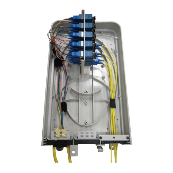
C16AK0009 REV.1 SLIMBOX-V, INDOOR ENCLOSURE-24F 3. Installation Type “Fan-out” Typical application of a fan-out consists of up to 24 fiber input cable conectorized with two MPO 12 fiber female connectors and twenty four (24) 1.6-2mm single fiber distribution cables connectorized with SC/UPC connectors. Other configurations are available upon request. - Page 5 C16AK0009 REV.1 SLIMBOX-V, INDOOR ENCLOSURE-24F Adapter Mtg. Brkt.® w/adapt. Base MPO to 12 Fiber SC/UPC Fan-Out (2X) Holding Plate Cable Anchor Rubber "L" Brkt. Grommet Plastic Retainer “Fan-out” style Fig. 1 assembly (installation kit and cover are not shown) pg. 4 ISSUE DATE 8/5/2016...
- Page 6 C16AK0009 REV.1 SLIMBOX-V, INDOOR ENCLOSURE-24F Fig.2 Typical installation of the “Fan-out” assembly pg. 5 ISSUE DATE 8/5/2016...
-
Page 7: Installation Type "Splitter
C16AK0009 REV.1 SLIMBOX-V, INDOOR ENCLOSURE-24F Cover, back view Cover Exploded view of the assembly (fan-outs not shown) Assy Top view Fig. 3 Components of the “Fan-out” type enclosure 4. Installation Type “Splitter” Typical application consists of 4 fiber input cable conectorized with SC/APC connectors, up to four (4) PLC 1:32 splitters and up to 128 fiber distribution cable or cables connectorized with and 16 MPO Female 8 Fiber connectors. - Page 8 C16AK0009 REV.1 SLIMBOX-V, INDOOR ENCLOSURE-24F Instructions 1. Open the closure and examine its content. Ref to Fig.3 and Fig. 5. All assemblies will contain : a. Fiber organizer spool b. Three rubber grommets with tree cable retainers (“L” shape brkt. with rectangular holes to pass plastic ties) c.
- Page 9 C16AK0009 REV.1 SLIMBOX-V, INDOOR ENCLOSURE-24F 2. Follow the enclosure installation steps from the paragraph entitled “Wall installation instructions (paragraph 2) 3. Cut the middle entry port rubber grommet following the molded in notch until you reach the center of the molded hole. Thread drop cable through the he just created opening. Use the cable aramid yarn, “L”...
- Page 10 C16AK0009 REV.1 SLIMBOX-V, INDOOR ENCLOSURE-24F Splitter Adapter bracket Splice tray Entry/Exit Port (3X) Fig. 5 Enclosure Type “Splitter” pg. 9 ISSUE DATE 8/5/2016...
- Page 11 C16AK0009 REV.1 SLIMBOX-V, INDOOR ENCLOSURE-24F “Direct” style enclosure- typical installation Fig.6 Note: White multi-fiber drop outdoor –indoor cable is spliced to the optical splitter (s) input fiber(s) and the splitter(s) outputs are spliced to the distribution cable(s). In Figure 6, the distribution cables are yellow.
-
Page 12: Installation Type "Splice Tray
C16AK0009 REV.1 SLIMBOX-V, INDOOR ENCLOSURE-24F Cover, back view Cover Exploded view of the assembly (fan-outs not shown) Assy Top view Fig. 7 Components- Enclosure type “Splitter” 5. Installation Type “Splice Tray” This type of installation provides ten splice trays. Each splice tray can accommodate 12 splice protectors or splitters. - Page 13 C16AK0009 REV.1 SLIMBOX-V, INDOOR ENCLOSURE-24F Instructions 1. Open the enclosure and examine its content. Refer to Fig. 6. All assemblies will contain: a. Fiber organizer b. Three rubber grommets with tree cable retainers (“L” shape brkt. with rectangular holes to pass plastic ties) c.
- Page 14 C16AK0009 REV.1 SLIMBOX-V, INDOOR ENCLOSURE-24F 2. Follow the enclosure installation steps from the paragraph entitled “Wall installation instructions (paragraph 2) 3. Cut an entry port rubber grommet following the molded in notch until you reach the center of the molded hole. Thread drop cable through the he just created opening. Use the cable aramid yarn, “L”...
- Page 15 C16AK0009 REV.1 SLIMBOX-V, INDOOR ENCLOSURE-24F Aramid yarn attached to "L" brkt. Fig. 9 Securing cable to “L” bracket – enclosure type “Splice” pg. 14 ISSUE DATE 8/5/2016...
- Page 16 C16AK0009 REV.1 SLIMBOX-V, INDOOR ENCLOSURE-24F Splice protector Splitter Drop cable Distribution cable Fig. 10 Typical “Splice” style installation Note: There are ten splice trays each capable of holding six splitters or twelve splice protectors. Usually, first two trays contain splitters and splice protectors and the remaining eight hold only splice protectors.
- Page 17 C16AK0009 REV.1 SLIMBOX-V, INDOOR ENCLOSURE-24F Cover, back view Cover Exploded view of the assembly Assy Top view Components – Enclosure type “Splice” w/o mounting kit Fig. 11 pg. 16 ISSUE DATE 8/5/2016...
-
Page 18: Installation Type "Direct
C16AK0009 REV.1 SLIMBOX-V, INDOOR ENCLOSURE-24F 6. Installation Type “Direct” This type of installation uses 12 or 24 fiber cables or multiple of them to the total of 48 connectorized ends. The acceptable cable sizes are up to 15 mm (0.6 in). The cables are either connectorized with SCA, SCU, LCA or LCU connector or not. - Page 19 C16AK0009 REV.1 SLIMBOX-V, INDOOR ENCLOSURE-24F hole. Slide the cable trough just made opening and replace the grommet. Tie the cable aramid yarn to the “L” bracket with a plastic tie. If the cable has a strength member, tie it to the one of the anchor bracket located at the top left and right of the base 4.
- Page 20 C16AK0009 REV.1 SLIMBOX-V, INDOOR ENCLOSURE-24F Adapter plate Strain with adapters member anchor brkt Splice Tray Fiber organizer Plastic Retainer Rubber Grommet “L” Brkt Fig. 12 Enclosure Installation type “Direct” (w/o cover and mounting kit) pg. 19 ISSUE DATE 8/5/2016...
-
Page 21: Technical Assistance
C16AK0009 REV.1 SLIMBOX-V, INDOOR ENCLOSURE-24F 7. Technical assistance OFS ensures that the technical information, statements, drawings and illustrations contained in this manual are reliable. However, the information may not be sufficient to install in certain conditions OFS reserves itself the right to make improvements, enhancements or changes to the products without prior notification including technical data and other information related to this product.
Need help?
Do you have a question about the OFS Slimbox 24 and is the answer not in the manual?
Questions and answers