Advertisement
Advertisement
Table of Contents

Related Manuals for Casio ML-2


Summary of Contents for Casio ML-2
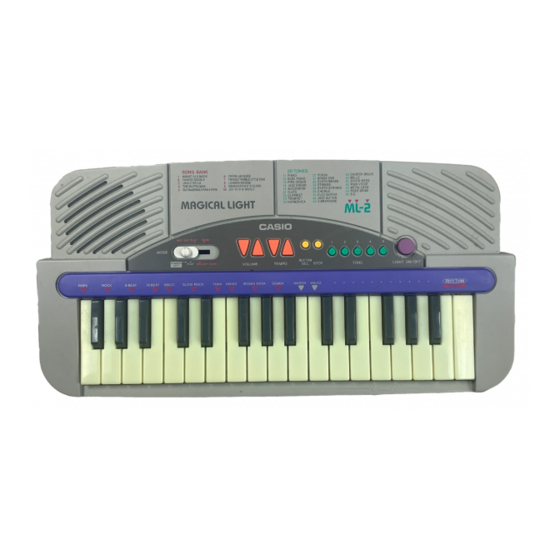
- Page 1 (with price) ML-2 ML-2 ELECTRONIC KEYBOARD...
-
Page 2: Table Of Contents
CONTENTS Specifications ......... . 1 Block Diagram . -
Page 3: Specifications
SPECIFICATIONS General Number of Keys: Illuminated Keys: White and Black keys Polyphonic: 2-note Preset Tones: Auto-Rhythms: Demonstration Tunes: Lesson Functions: 3 modes; Demo, Any-Key Play, Melody Guide Built-In Speaker: 8.0 cm dia. 1.0 W Input Rating: 1 pce. Output Jack [Output Impedance: 100 Ω, Output Voltage: 1.6 V (rms)], Terminals: AC Adapter Jack (DC 7.5 V) Power Source:... -
Page 4: Block Diagram
BLOCK DIAGRAM Illuminated Keyboard LX0~LX3 LY0~LY7 LEDs Output Jack KO0~KO11 Amplifier MSM6521-11 Filter AN8053N LSI1 Speaker KI0~KI7 VDD 5.6V AVDD 5.6V Power Supply Circuit Oscillator T1, D4 Switches Nomenclature of Keys F#3 G#3 A#3 C#4 D#4 F#4 G#4 A#4 C#5 D#5 F#5 G#5 A#5 G3 A3 B3 C4... -
Page 5: Circuit Description
CIRCUIT DESCRIPTION Key Matrix Volume Volume Light Down On/Off Rhythm Tempo Tone 1 Stop Down Rhythm Tempo Tone 2 Tone 3 Tone 4 Tone 5 Select Melody Any Key Demo Play Guide Play Keyboard LED Matrix — 3 —... - Page 6 CPU (LSI1: MSM6521-11) Containing a sound data ROM and a DAC (Digital to Analog Converter), the CPU provides sound wave- form in accordance with the pressed key and selected tone. The CPU also drives LEDs in the illuminated keyboard directly. The following table shows the pin functions of LSI1. Pin No.
-
Page 7: Troubleshooting
Power Supply Circuit The power supply circuit regulates a constant output voltage +5.6V by T1 and D4. VDD +5.6V 2SD1858Q,R Power Switch DC +7.5 V Input AVDD +5.6V TROUBLESHOOTING Nature of Trouble Faulty Block Checkpoint No power Power Supply Circuit Base of T1 should receive +6 V. -
Page 8: Schematic Diagrams
SCHEMATIC DIAGRAMS JCM605-KY1M — 6 —... - Page 9 JCM605-LD1M JCM605-LD2M — 7 —...
- Page 10 JCM605-MA1M/MA2M — 8 —...
-
Page 11: Pcb View And Major Waveforms
PCB VIEW AND MAJOR WAVEFORMS Key A3 OFF (5.6V) Key A3 ON Sound signal output LED drive signal LY7 Key scan signal KO0 MSM6521-11 pin29 JC connector pin1 MSM6521-11 pin39 Key scan signal KO7 Power amp output LED drive signal LX3 MSM6521-11 pin46 AN8053N pin 1 JC connector pin11... -
Page 12: Exploded View
EXPLODED VIEW — 10 —... -
Page 13: Ic And Transistor Lead Identification
IC LEAD IDENTIFICATION LSI1: MSM6521-11 AGND KO10 AVDD KO11 RESET TEST3 TEST2 TEST1 GND1 Ø2 COSO Ø1 COSI GND2 GND1 LVDD2 IC1: AN8053N T1: 2SD1858Q, R T2, T3: 2SC1740SQ — 11 —... -
Page 14: Parts List
PARTS LIST ML-2 Notes: Prices and specifications are subject to change with- out prior notice. As for spare parts order and supply, refer to the "GUIDEBOOK for Spare parts Supply", published seperately. The numbers in item column correspond to the same... - Page 15 FOB Japan Item Code No. Parts Name Specification N.R.Yen Unit Price Main PCB Ass'y LSI1 2011 7497 LSI MSM6521-11 2114 3269 IC AN8053N 2253 0448 Transistor 2SD1858Q,R-TV6-T T2/3 2220 1387 Transistor 2SC1740SQ-TP-T 2 10 2390 0371 Diode DSK10B-BT-T 1 10 2390 1323 Diode RB100A-T32-T 1 10...
- Page 16 FOB Japan Item Code No. Parts Name Specification N.R.Yen Unit Price Mechanical Parts 4317 5081 Blank PCB JCM605-KY1 M211780A-1 3831 0378 Speaker EAS-8P149BD 6922 6930 Slide knob 521 M311280-4 6922 7670 Slide knob 521 M311280-5 6922 6821 L-LIMIT-LNM32 M412337A-1 6922 6810 U-LIMIT-LNM32 M412336-1 6922 6791 Upper case (Black) M211786A*2...
- Page 17 MA0700941A...
Need help?
Do you have a question about the ML-2 and is the answer not in the manual?
Questions and answers