Advertisement
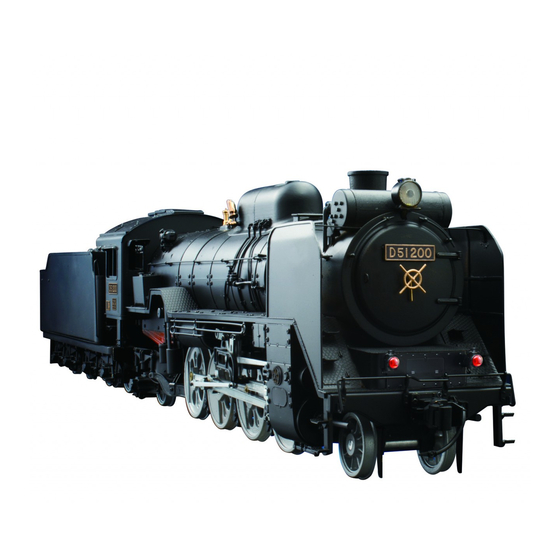
D51 200 Steam Locomotive: STEP BY STEP
The third wheels set
Your parts
Wheels
Axle boxes A × 2
Axle boxes B × 2
Axle box guards × 2
Bushes × 2
2 x 6mm screws × 7
Required tools
Masking tape
Pliers
Tweezers
Phillips screwdriver
File
Stage 25
Third wheels set
1
Preparing the parts
Temporarily assemble axle boxes A
and B. Place some masking tape on the
flat area of the temporarily assembled
axle boxes, as shown above.
Place the assembled axle boxes over the axle of the
wheels, inside of the bush at each end of the axle, with
the long part of the axle boxes closer to the wheels.
™
51
Advertisement
Table of Contents

Related Manuals for Model Space D51 200

Summary of Contents for Model Space D51 200
- Page 1 D51 200 Steam Locomotive: STEP BY STEP Stage 25 ™ The third wheels set Third wheels set Your parts Preparing the parts Required tools Wheels Axle boxes A × 2 Masking tape Axle boxes B × 2 Pliers Axle box guards × 2 Tweezers Bushes ×...
-
Page 2: Fitting The Wheels
D51 200 Steam Locomotive: STEP BY STEP ™ Fitting the wheels Fitting the guards Turn the assembly over and place the wheels into the cut-outs at the front of the underframe. Position the wheels so that the underframe rests in the groove of the axle Place the first axle box guard boxes. - Page 3 D51 200 Steam Locomotive: STEP BY STEP Stage 26 ™ The fourth wheels set Fourth wheels set Your parts Fitting the wheels Assemble axle boxes A and B. Place the assembled axle boxes over the axle of the wheels, with...
-
Page 4: Preparing The Parts
D51 200 Steam Locomotive: STEP BY STEP ™ Preparing the parts Check over the coupling rods for any burrs or casting flash. Remove any you find with a file, and then smooth with wet and dry paper. Remove the coupling rod, rod pin and bush from the first wheels. - Page 5 D51 200 Steam Locomotive: STEP BY STEP ™ Assembling the coupling rods Combine the front end of the coupling rod from Rod pin (small) Stage 26 with the back Hold the left coupling rods end of the rod assembly, from Stages 4 and 24, as shown,...
-
Page 6: Connecting Rods
D51 200 Steam Locomotive: STEP BY STEP Stage 27 ™ The connecting rods Connecting rods Your parts Preparing the parts In order to fit the connecting rod, you will need to remove the crosshead cover. Use the wrench that Required tools... - Page 7 D51 200 Steam Locomotive: STEP BY STEP ™ Fitting the connecting rod Fitting the eccentric arms Position the left connecting rod Lift the connecting over wheels 1-3, rod off of the pin of placing the larger the third wheels and...
- Page 8 D51 200 Steam Locomotive: STEP BY STEP Stage 28 ™ The valve gear The radius rods and expansion links Your parts Assembling the expansion links Place one of the assembled Using the photo on expansion links over the split Expansion link...
- Page 9 D51 200 Steam Locomotive: STEP BY STEP ™ Assembling the valve gear Mounting the gears Expansion link Right side Piston valve spindle 2 × 3.6mm screw Combination lever Connecting link 2 x 3.6mm screw Expansion link Motion frame Re-fit the left motion plate to the side of...
Need help?
Do you have a question about the D51 200 and is the answer not in the manual?
Questions and answers