Table of Contents
Advertisement
Quick Links
Advertisement
Table of Contents

Related Manuals for PR electronics 2240

Summary of Contents for PR electronics 2240
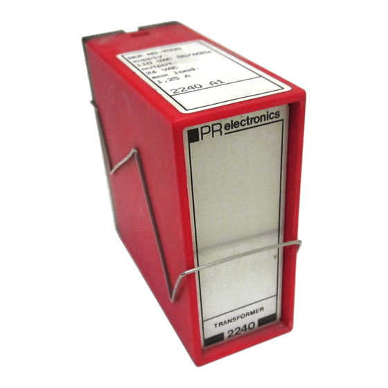
- Page 1 PERFORMANCE MADE SMARTER Product manual 2240 Transformer T E M P E R AT U R E I . S . I N T E R FA C E S CO M M U N I C AT I O N I N T E R FA C E S...
- Page 2 6 Product Pillars to meet your every need Individually outstanding, unrivalled in combination With our innovative, patented technologies, we make signal conditioning smarter and simpler. Our portfolio is composed of six product areas, where we offer a wide range of analog and digital devices covering over a thousand applications in industrial and factory automation.
-
Page 3: Table Of Contents
Transformer 2240 Table of contents Warning .................... -
Page 4: Warning
General mounting, wire connection and disconnection. HAZARD- Troubleshooting the device. Repair of the device and replacement of circuit breakers must be done by PR electronics A/S only. VOLTAGE Warning To keep the safety distances, devices with two built-in relays must not be connected to both hazardous and non-hazardous voltages on the same device’s relay contacts. -
Page 5: Safety Instructions
Should there be any doubt as to the correct handling of the device, please contact your local distributor or, alternatively, PR electronics A/S www.prelectronics.com Mounting and connection of the device should comply with national legislation for mounting of electric materials, i.a. wire cross section, protective fuse, and location. -
Page 6: How To Dismantle System 9000
How to dismantle system 9000 The back panel of the device is detached from the housing by way of a screw-driver as shown in picture 1. On a device with knobs, these must be removed before the PCB can be taken out as shown in picture 2. After this, the back panel can be pulled out together with the PCB, but please notice the position of the PCB as there is a number of different positions in the house. -
Page 7: Application
The load diagram shows the relation between the ambient temperature and maximum VA output. Mounting • The 2240 is for standard 11-pole socket mounting in all positions. To achieve maximum cooling of the device, mounting in a vertical position at a distance of 10 mm between neighbouring units is recommended. •... -
Page 8: Order
Order Type Input Output 2240 115 VAC 24 VAC 230 VAC 12 VAC Technical data Environmental conditions: Specifications range ........-20°C to +60°C Storage temperature . -
Page 9: Block Diagram
Block diagram Output P Supply P Supply N Output N 2240 Load diagram for max. power output Output VA Ambient temperature °C 2240V102-UK... -
Page 10: Document History
Document history The following list provides notes concerning revisions of this document. Rev. ID Date Notes 1947 Production of version 2240X0 discontinued. 2240V102-UK... - Page 11 We are near you, all over the world Our trusted red boxes are supported wherever you are All our devices are backed by expert service and a 5-year business with a global reach. This means that we are warranty. With each product you purchase, you receive always nearby and know your local markets well.
- Page 12 Benefit today from PERFORMANCE MADE SMARTER PR electronics is the leading technology company specialized in making industrial process control safer, more reliable and more efficient. Since 1974, we have been dedicated to perfecting our core competence of innovating high precision technology with low power consumption.
Need help?
Do you have a question about the 2240 and is the answer not in the manual?
Questions and answers