Table of Contents
Advertisement
Quick Links
Advertisement
Table of Contents

Subscribe to Our Youtube Channel
Related Manuals for Matrox Vio


Summary of Contents for Matrox Vio
- Page 1 Artisan Technology Group is your source for quality new and certified-used/pre-owned equipment SERVICE CENTER REPAIRS WE BUY USED EQUIPMENT • FAST SHIPPING AND DELIVERY Experienced engineers and technicians on staff Sell your excess, underutilized, and idle used equipment at our full-service, in-house repair center We also offer credit for buy-backs and trade-ins •...
- Page 2 Matrox Vio Installation and Hardware Reference Manual no. Y10995-101-0102 January 3, 2013...
- Page 3 © Copyright Matrox Electronic Systems Ltd., 2006-2013. All rights reserved. Limitation of Liabilities: In no event will Matrox or its suppliers be liable for any indirect, special, incidental, economic, cover or consequential damages arising out of the use of or inability to use the product, user documentation or related...
-
Page 4: Table Of Contents
Inspecting the Matrox Vio Duo package ........ - Page 5 Global information ..........42 Technical features of Matrox Vio Duo ......42 Electrical specifications .
- Page 6 Major revisions of Matrox Vio ........
-
Page 8: Chapter 1: Introduction
Chapter Introduction Chapter 1: This chapter briefly describes the key features of the Matrox Vio frame grabber, as well as the software that can be used with the board. -
Page 9: Matrox Vio
(HD-15) x4 PCIe interconnect This manual will explain how to install the Matrox Vio Duo, as well as the features and the necessary technical information about Matrox Vio Duo. Everything that applies to Matrox Vio Duo also applies to Matrox Vio Analog, with the exception... -
Page 10: Acquisition Features
Matrox Vio Acquisition features Matrox Vio Duo can acquire video data from an SD or HD analog or digital video source; the analog path utilizes a multi-format decoder for capturing video data, whereas the digital path uses a multi-rate deserializer. The table below summarizes... -
Page 11: Memory
Host. Data transfer Matrox Vio Duo can exchange data with the Host at a peak transfer rate of up to 800 Mbytes/sec when used in a four lane PCIe slot. Internal data paths allow for transfer of live video to on-board memory, Host memory, or auxiliary display. - Page 12 (template-based and feature-based), code recognition and verification (1D, 2D and composite code types), 3D reconstruction, and color analysis. MIL applications are easily ported to new Matrox hardware platforms and can be designed to take advantage of multi-processing and multi-threading environments.
-
Page 13: Essentials For Getting Started
• Processor with an Intel 32-bit architecture (IA32) or equivalent. Please refer to the Matrox Imaging website for information on compatible chipsets. • A CD drive, and a hard disk or network drive on which to install the Matrox Vio Duo software. -
Page 14: Handling Components
Inspecting the Matrox Vio Duo package • A flat ribbon cable to interface the frame grabber with the input adapter board. • A CD with the Matrox Vio Duo Installation and Hardware Reference manual (this document). You might have also ordered one of the following: Available separately •... -
Page 15: Installation
MIL, ActiveMIL, ActiveMIL-Lite, or Matrox Inspector. ❖ Note that, although other software products might be available to operate Matrox Vio Duo, the discussion throughout this manual is based in terms of Matrox Imaging software products. When the term Host is used in this manual, it refers to the host computer. -
Page 16: Chapter 2: Hardware Installation
Chapter Hardware Chapter 2: Installation This chapter explains how to install the Matrox Vio Duo board in your computer. -
Page 17: Installing The Matrox Vio Duo Board
16 Chapter 2: Hardware Installation Installing the Matrox Vio Duo board Before installing your Matrox Vio Duo board, some precautionary measures must be taken. Turn off the power to your computer and all its peripherals, and drain static electricity from your body (by touching a metal part of the computer chassis). - Page 18 This will require an additional empty slot. This slot can be any type of PCI slot and need not be adjacent to the Matrox Vio Duo board. Note that the expanded video input adapter board does not plug into a slot’s PCI/PCI-X/PCIe connector;...
- Page 19 5. Anchor the board to the chassis. Replace the screw(s) removed in step 3, if any. 6. If required, install the expanded video input adapter board of the Matrox Vio Duo board as described in the Installing the expanded video input adapter board section later in this chapter.
-
Page 20: Installing The Expanded Video Input Adapter Board
Connect one end of the flat ribbon cable to the 40-pin internal connector of the Matrox Vio Duo board. To do so, position the ribbon cable so that the red colored stripe is on the same side as the bracket of the board. In this position, the connector on only one end of the cable will latch properly. - Page 21 20 Chapter 2: Hardware Installation 3. Slide the bracket into the opening at the back of the selected slot. The expanded video input connector should now be accessible from outside of the chassis. 4. Secure the adapter board’s bracket to the chassis. Replace the screw(s) removed in the previous section, if any.
-
Page 22: Connecting External Devices
Connecting external devices Connecting external devices The Matrox Vio Duo board has five external interface connectors on its main bracket and one internal connector. The expanded video input adapter board has five external interface connectors and one internal connector. Matrox Vio Duo main bracket: connectors •... - Page 23 Matrox. You can use a standard BNC coaxial cable to connect to an expanded analog video input connector. Note that this cable is not available from Matrox. You can use a VGA-compatible cable to connect the external analog video output connector to a high-resolution TV monitor.
- Page 24 HD/SD-SDI format. Recall that both connectors output the same video stream. For a clear signal, you should use a shorter cable as the data rate increases. Note that this cable is not available from Matrox.
- Page 25 24 Chapter 2: Hardware Installation...
-
Page 26: Chapter 3: Matrox Vio Duo Hardware Reference
Chapter Matrox Vio Duo Chapter 3: Hardware Reference This chapter explains the architecture of the Matrox Vio Duo hardware, as well as the features and modes of operation. -
Page 27: Matrox Vio Duo Hardware Reference
This chapter provides information on the hardware architecture of Matrox Vio Duo, as well as the available features and operating modes supported by the board. The chapter is divided into three sections. The first section describes the Matrox Vio Duo hardware associated with the acquisition of images, while the second section discusses the video controller. -
Page 28: Matrox Vio Duo Acquisition Section
Matrox Vio Duo acquisition section Matrox Vio Duo acquisition section Matrox Vio Duo supports acquisition of both analog and digital video. Although you can acquire data from only one video source at a time, you can attach several video sources and switch between them. The board features six software-selectable input channels: four for analog video and two for digital video. -
Page 29: Analog Acquisition
28 Chapter 3: Matrox Vio Duo Hardware Reference Analog acquisition The analog acquisition path captures SD (CVBS, RGB, Y/C, or YPbPr) or HD (RGB or YPbPr) analog video and converts it to 20-bit YCbCr data. Low-pass filter Analog video signals acquired by the expanded video input adapter board pass through a 4th order Butterworth filter in a low-pass filtering stage. - Page 30 Matrox Vio Duo acquisition section A built-in multiplexer allows for connectivity to multiple video sources and internal current and voltage clamps ensure the removal of DC offsets from the input video signal. Three 12-bit A/D converters then digitize the analog video signal into a 20-bit YCbCr pixel stream.
-
Page 31: Video Controller
30 Chapter 3: Matrox Vio Duo Hardware Reference Video controller The video controller processes and formats digitized video received from the decoder or the deserializer, before transferring the video data to an auxiliary display or to the Host. Video data can be output to an auxiliary display in the same format that it was acquired, or it can be transferred to the Host in either monochrome, BGR24 packed, BGR32 packed, or YUV pixel formats. -
Page 32: Acquisition Interface
Using the PCI-X interface, Matrox Vio Duo can access Host DMA memory (physically contiguous, non-paged memory). An advantage of DMA memory is that a bus mastering device (such as Matrox Vio Duo) can access this memory without Host intervention. Overlay composer The overlay composer overlays image(s) onto image data. -
Page 33: Color Space Converter And Formatter
32 Chapter 3: Matrox Vio Duo Hardware Reference image are displayed unless they are equal to the keying color, in which case the corresponding pixels of the underlay image are displayed instead. The overlay image size should equal the size of the underlay image to avoid corrupting the image. -
Page 34: Pci-X Interface
PCI-X to PCIe bridge Matrox Vio Duo is a PCIe board. It connects to the 4x PCIe connector of a 4-lane PCIe slot on the motherboard. PCIe is a high-speed serial transmission protocol based upon the PCI bus standard. However, since Matrox Vio Duo implements PCI-X bus technology to interface with on-board components, a PCI-X to PCIe bridge is installed on the board to translate between the two protocols. -
Page 35: Matrox Vio Duo Display Section
34 Chapter 3: Matrox Vio Duo Hardware Reference Matrox Vio Duo display section Matrox Vio Duo can output video to an auxiliary display in either analog mode, digital mode , or both simultaneously. In either mode, video is output to the display at the original acquisition resolution. -
Page 36: Appendix A: Glossary
Appendix A: Glossary Appendix A: This appendix defines some of the specialized terms used in the Matrox Vio SDI documentation. - Page 37 36 Appendix A: Glossary Glossary • Band One of the surfaces of a buffer. A grayscale image requires just one band. A color image requires three bands, one for each color component. • Bandwidth A term describing the capacity to transfer data. Greater bandwidth is needed to sustain a higher transfer rate.
- Page 38 • DDR SDRAM Double Data Rate Synchronous Dynamic Random Access Memory. A type of memory used for image capture and processing. SDRAM allows the Matrox Solios FPGA to access data at very high speed, which is important for I/O-bound functions.
- Page 39 38 Appendix A: Glossary • Exposure time Refers to the period during which the image sensor of a video source is exposed to light. As the length of this period increases, so does the image brightness. • Field One of the two halves that together make up the image grabbed from an interlaced video source.
- Page 40 Glossary • Interlaced scanning Describes a transfer of data in which the odd-numbered lines of the source are written to the destination buffer first, and then the even-numbered lines (or vice-versa). See also progressive scanning. • Latency The time from when an operation is started to when the final result is produced. •...
- Page 41 40 Appendix A: Glossary • Reference levels The zero and full-scale levels of an analog-to-digital converter. Voltages below a black reference level are converted to a zero pixel value; voltages above a white reference level are converted to the maximum pixel value. Together with the analog gain factor, the reference levels affect the brightness and contrast of the resulting image.
-
Page 42: Appendix B: Technical Information
Appendix B: Technical Appendix B: information This appendix contains information that might be useful when installing your Matrox Vio Duo board. -
Page 43: Board Summary
Important - A proper power supply. Refer to the Electrical specifications section (next page). To learn more about appropriate chipsets, refer to the Matrox Imaging website. Technical features of Matrox Vio Duo • Can acquire data from one video source at a time. -
Page 44: Electrical Specifications
1.6 Gbytes/sec of memory bandwidth and 64-bit wide data bus. • 1 Mbyte flash EEPROM for storage of board data. Electrical specifications Matrox Vio Duo (applies to PCB# Y7231-01) Operating voltage and current Typical: 3.3 V, 2.48 A = 8.18 W Typical 12.0 V, 0.73 A = 8.76 W... -
Page 45: Connectors On Matrox Vio Duo
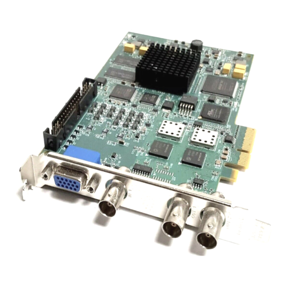
44 Appendix B: Technical information Connectors on Matrox Vio Duo The Matrox Vio Duo board has several interface connectors. The board has two BNC connectors for digital video input, two BNC connectors for digital video output, and a high density 15-pin (HD-15) connector for analog video output on its main bracket. -
Page 46: External Digital Video Input Connectors
Connectors on Matrox Vio Duo External digital video input connectors The external digital video input connectors are standard, low profile, 75 Ohm impedance BNC connectors, used to receive HD/SD-SDI video signals. The connectors are shown in the following image. IN 1... -
Page 47: External Digital Video Output Connectors
46 Appendix B: Technical information External digital video output connectors The digital video output connectors are standard, low profile, 75 Ohm impedance BNC connectors, used to send HD/SD-SDI video signals. The connectors are shown in the following image. Their pin assignment is as follows: Signal Description HD/SD_SDI_OUT0... -
Page 48: External Analog Video Output Connector
Connectors on Matrox Vio Duo External analog video output connector The external analog video output connector is a high density 15-pin (HD-15) female connector used to output video signals to an auxiliary display. The connector is shown in the following image. -
Page 49: Internal Expanded Video Input Connector
48 Appendix B: Technical information Internal expanded video input connector The internal expanded video input connector is a standard, 0.1" spacing, 40-pin male connector, used to receive video input signals. It connects to a similar connector on the expanded video input adapter board via a 40-pin flat ribbon cable. - Page 50 Connectors on Matrox Vio Duo Signal Description Ground. No connection. Ground. No connection. Ground. CSYNC_IN Analog component sync input. Ground. Ground. Ground. VID_IN0 Y component of YPbPr input, G component of RGB input, or Y component of Y/C input. Ground.
-
Page 51: Expanded Analog Video Input Connectors
50 Appendix B: Technical information Expanded analog video input connectors The expanded analog video input connectors are five standard, low profile, 75 Ohm impedence BNC connectors, used to receive video input signals. The connectors are shown in the following image: The pin assignment for the connectors are as follows: Signal Description... - Page 52 Appendix C: Listing of Matrox Vio Appendix C: boards...
- Page 53 52 Appendix C: Listing of Matrox Vio boards Major revisions of Matrox Vio Board Part# Version# Description Matrox Vio Analog VIO7IAOA* • Initial product version. ROHS compliant. • Upgrade analog video decoder version. Matrox Vio Duo VIO7ISAOSA* • Initial product version. ROHS compliant.
- Page 54 26 horizontal blanking period 38 synchronization 38 data transfer 10 DCF 37 decoder, multi-format 9 deserializer, multi-rate 9 installation digital path 9 expanded video input adapter board 19 digitizer 27 Matrox Vio board 16 dimensions 43 overview 14...
- Page 55 40 revisions 52 Video controller 30 software 10 static images 10 technical features 42 Y/C 28 Matrox Vio Analog, differences with Matrox Vio Duo 8 – YCbCr 29 memory, acquisition 10 YPbPr 28 MIL. See Matrox Imaging Library YUV 9...
- Page 56 Regulatory Compliance FCC Compliance Statement Warning Changes or modifications to these units not expressly approved by the party responsible for the compliance could void the user's authority to operate this equipment. The use of shielded cables for connections of these devices to other peripherals is required to meet the regulatory requirements.
- Page 57 Bitte wenden Sie sich an dem Matrox-Website (www.matrox.com/environment/weee) für Recycling Informationen. (Italiano) Informazioni per gli utenti europei – Direttiva sui rifiuti di apparecchiature elettriche ed elettroniche (RAEE) Si prega di riferirsi al sito Web Matrox (www.matrox.com/environment/weee) per le informazioni di riciclaggio.
- Page 58 Limited Warranty Refer to the warranty statement that came with your product.
- Page 60 Artisan Technology Group is your source for quality new and certified-used/pre-owned equipment SERVICE CENTER REPAIRS WE BUY USED EQUIPMENT • FAST SHIPPING AND DELIVERY Experienced engineers and technicians on staff Sell your excess, underutilized, and idle used equipment at our full-service, in-house repair center We also offer credit for buy-backs and trade-ins •...
Need help?
Do you have a question about the Vio and is the answer not in the manual?
Questions and answers