Table of Contents
Advertisement
Quick Links
Advertisement
Table of Contents

Related Manuals for Stensat Sten-Bot Robot Kit

Summary of Contents for Stensat Sten-Bot Robot Kit
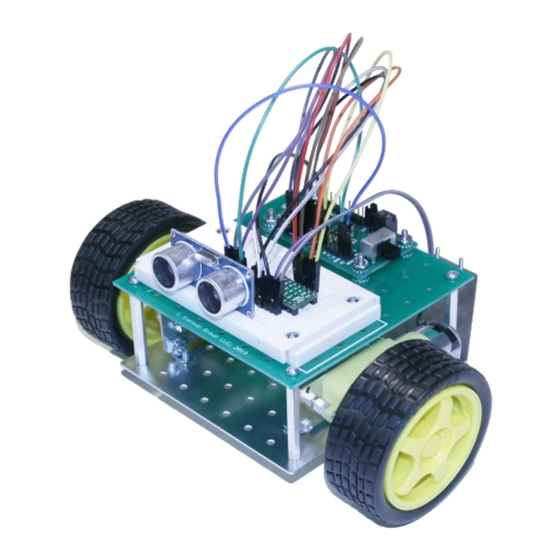
- Page 1 Sten-Bot Robot Kit Stensat Group LLC, Copyright 2013...
-
Page 2: Legal Stuff
Legal Stuff Stensat Group LLC assumes no responsibility and/or liability for the ● use of the kit and documentation. There is a 90 day warranty for the Sten-Bot kit against component ● defects. Damage caused by the user or owner is not covered. -
Page 3: Program Overview
Program Overview Assemble Kit ● Motor assembly ● Base plate assembly ● Electronics plate assembly ● Programming ● Calibration ● Running the Maze ●... -
Page 4: Parts List
Parts List 4 – 3/16” 4-40 screws 1 – processor board ● ● 8 – 1/4” 4-40 screws 1 – solderless bread board ● ● 8 – 1/2” 4-40 screws 10 – jumpers ● ● 4 – 1” 4-40 screws 1 –... -
Page 5: Tools Needed
Tools Needed Philips screw driver ● 1/4 inch nut driver ● Jeweler blade screw driver ●... - Page 6 How the Robot Works 4 AA Batteries power the robot. ● Battery Battery The processor board executes a ● program to control the motors and operate the ultrasonic sensor. The motor controller supports two Processor ● Processor Board motors. Board Two control signals are used to ●...
-
Page 7: Motor Assembly
Motor Assembly The two wheels need to be mounted to ● the base plate. A motor mount adapter needs to be assembled. Notice that one side of the motor has a ● circular plastic shape sticking out. Insert ¼ inch screw as shown and secure the ¼... - Page 8 Motor Assembly Align the motor mount adapter plate to the side of the motor. Secure the ● back end with 1 inch long screws Secure the top screw with a nut. For the bottom screw, install a right angle ● bracket.
- Page 9 Motor Assembly Assemble the second motor in the mirror image of the first. ● The two motors should look like below. ● 1” x 2 1” x 2 ¼” 4-40 ¼” 4-40 ¼“ standoffs...
-
Page 10: Mounting The Motors
Mounting the Motors Align the brackets to the holes shown in ● the picture. Secure with two 3/16 inch screws from ● the bottom side. You may need to loosen the screws on ● the motor mount brackets to align the brackets. - Page 11 Robot Plate Assembly With the motors installed, mount the caster at the rear using the two holes ● and the screws from the caster parts. Secure the caster holder with the two screws and nuts. ●...
- Page 12 Electronics Base Plate Base plate is for mounting ● solderless bread board and processor board Solderless bread board is to be ● mounted in the marked rectangular area . Use the 1/2 inch screws and ● nuts to secure as shown in the next page.
- Page 13 Processor Board Mount The process board is mounted ● differently. Insert screws from the back side ● and install a nut on each screw. The nuts will serve as standoffs for the processor board.
- Page 14 Electronics Base Plate Assembly Place the processor board ● on top of the nuts. Insert another set of four ● nuts to secure the processor board.
- Page 15 Mounting Electronics Plate Install four 1.5 inch long standoffs with the threaded end inserted into the ● plate. Secure with nuts from the bottom side of the plate. ● 1.5 inch 1.5 inch Standoffs Standoffs...
- Page 16 Mounting the Electronics Plate Secure the electronics plate on top of the standoffs using 4-40 1/4 inch ● screws. ¼ inch ¼ inch Screws Screws...
- Page 17 Installing the Battery Holder To install the battery holder, take two pieces of double sided tape and stick ● them to the underside of the battery holder. Peel the other side and stick it to the base plate as shown. ●...
-
Page 18: Installing The Wheels
Installing the Wheels The wheels are installed by pressing them onto the geared ● motor shaft. The shaft is keyed. Press fit the wheel onto the shaft. -
Page 19: Processor Specifications
Processor Specifications Compatible to 8MHz ATMEGA168 arduino boards ● 8MHz operating speed ● 16KB Program memory ● 1KB Ram ● 512 Byte EEPROM ● 6 Digital IO ports ● Can be configured as input, output, Servo, PWM ● 6 Analog ports ●... - Page 20 Processor Board Pinout Digital Pins ● D3, D5, D6, D9, D10, D11 ● Can be configured as ● Digital Pins INPUT ● OUTPUT ● Servo ● ● Each digital pin has 5V and GND in a ● row. Allows servos to be connected ●...
- Page 21 Processor Board Pinout UART ● Uses same transmit and receive ● signals as USB port Use only when not plugged into USB ● port UART Supports up to 57600 baud ● 5V and ground included and always ● powered Transmit Receive ●...
- Page 22 Processor Board Layout Power Switch Power Switch ● Switches external power on and off ● When USB selected, switch does not ● function Micro USB Port ● Used for programming and UART ● interfacing with USB host (PC) Power source selection ●...
- Page 23 Arduino Software Download development software from ● www.arduino.cc ● Follow instructions on installation ● The processor operates at 8MHz ● In the arduino program select menu “Tools” ● Select “Board” ● Select “Arduino Pro or Pro Mini (3.3V 8MHz) with ATMega168 ●...
- Page 24 Using Arduino This is the arduino software ● It has a text editor and ● compiler Verify Save Code Open It uploads programs to the ● Serial Program Upload Monitor processor board Code Area for entering code It has a serial monitor for ●...
- Page 25 First Program to Test Enter the program in the editor on the ● void setup() right. Do not copy and paste from the pdf file. It doesn't work. The Serial.begin(9600); compiler is case sensitive so pay attention to capitalized letters. void loop() Plug the processor board into the USB ●...
- Page 26 Arduino Programming Basics The program is made up of two ● functions. setup() function is run at reset or ● void setup() power up and only once. Serial.begin(9600); It is used to initialize all the ● needed interfaces and any parameters.
- Page 27 How the Solderless BreadBoard Works The solderless bread board allows circuits to be quickly connected. ● Each row of holes that go left to right on the top and bottom are all connected ● together. The columns of 5 holes are all connected together. ●...
-
Page 28: Using Leds
Using LEDs The LED is a polarized device and only works ● in one direction. The positive pin on the LED is the longer pin. ● LEDs need the current to be limited. Include a ● supplied 270 ohm resistor in series with the LED when connecting. - Page 29 First Circuit The first circuit will connect the LED straight to 5 volts ● so the LED will always be lit when there is power. The schematic for the circuit is shown to the right. ● The symbol at label R1 is for the resistor. ●...
- Page 30 Wiring Diagram for LED Resistor Long lead...
- Page 31 digitalWrite() The digitalWrite() function controls a pin and can set it high or low. ● When set high, the pin is set to 5 volts. ● When set low, the pin is set to 0 volts. ● The function is written as ●...
- Page 32 Connecting the LED to a Digital Pin Move the red wire from the 5V pin to digital ● pin 3. (shown on next page) void setup() The LED is not lit at this time because the ● pinMode(3,OUTPUT); digital pin 3 needs to be programmed to generate a voltage.
- Page 33 LED Connected to Port 3 Digital Pin...
-
Page 34: Photo Cell
Photo Cell The photo cell is a light sensitive device ● that changes its resistance based on light intensity. The photocell can be used in a simple ● voltage divider circuit with another resistor. The resistor is 4.7Kohms. The photo resistor will have a resistance ●... - Page 35 Photo Cell Program void setup() The program to the right will get an ADC ● value from analog port 0. Serial.begin(9600); To measure the voltage, the function ● analogRead(port) is used. void loop() Six ports are available on the processor ●...
-
Page 36: Motor Control
Motor Control Dual H-Bridge Driver is used to control the motors. It uses four transistors to ● control the polarity of the voltage supplied to the motor. Below shows the H-bridge driver circuit and the current flows. ●... - Page 37 Motor Control Controlling the motors is the same as controlling the LED except two signals ● are needed. With two signals, you can control the direction of the motors and turn them ● on and off. The following pages will describe how to hook up the motors. ●...
- Page 38 Motor Control Dual H-Bridge Driver is used to control the motors. It uses four transistors to control the polarity of the voltage supplied to the motor. The transistors are used as switches turning on and off. Below shows the H-bridge driver circuit and the current flows.
- Page 39 Motor Control To make the motor turn on one direction, two switches need to be turned on to let power get to the motor. One switch connects the positive side of the battery to to one side of the motor and another switch connects the negative side to the other side of the motor.
- Page 40 Motor Control Flip all the switches to the opposite position and the motor turns in reverse. Notice the polarity signs on the motor switched sides. Motor Battery...
- Page 41 H-Bridge Driver The motor controller module consists of two H-bridge ● drivers to control two motors. The circuit side is shown at the top right. The square ● block in the center contains the two motor drivers. The bottom picture shows the signal names next to ●...
- Page 42 How the H-Bridge Driver Works This drawing shows how the H-Bridge driver works. Only one is shown. ● There are two signals that control the direction and operation. Control logic ● decodes the two signals and turns on the appropriate switches to control the motor.
- Page 43 How the H-Bridge Driver Works When AIN1 is set to logic 1, the motor drives in the forward direction. ● You will notice that setting AIN1 = 1, and AIN2=0 turns on two signals that ● turn on the two switches. AIN1=1 Control Motor...
- Page 44 How the H-Bridge Driver Works When AIN1 is set to logic 1, the motor drives in the forward direction. ● You will notice that setting AIN1 = 1, and AIN2=0 turns on two signals that ● turn on the two switches. AIN1=0 Control Motor...
- Page 45 How the H-Bridge Driver Works When you set both AIN1 and AIN2 to logic 1, you get a breaking action. ● This turns on the two bottom switches which shorts the motor connections ● together. The inductance created by the motor turning in one direction will power the motor to turn in the opposite direction.
- Page 46 Mount the Motor Controller Insert the motor controller module into the solderless breadboard as shown. ● The rows of pins need to on either side of the gap down the center of the board.
- Page 47 Wiring The Motor Controller Use the jumper wires to connect the ● motor controller. First connect power ● Connect a wire from GND on the ● motor controller to GND at Signal D6 on the processor board. Connect a wire from VCC on the ●...
- Page 48 Motor Controller Wiring Diagram...
-
Page 49: Wiring The Motors
Wiring the Motors Now connect the motors. ● Connect the left motor wires to OUT B1 and B2 ● Connect the right motor wires to OUT A1 and A2 ● Don't worry if they are wired backwards. That will be corrected next. ●... - Page 50 Wiring Diagram for Motors Left Motor Right Motor...
-
Page 51: Testing The Motors
Testing the Motors To operate the motors, A1 or A2 need to be ● void setup() set high or low. Operation is simple if A1 and A2 are set off, pinMode(6,OUTPUT); ● pinMode(9,OUTPUT); the motors do not operate. pinMode(10,OUTPUT); If A1 is set high and A2 is low, the motors will pinMode(11,OUTPUT);... -
Page 52: Direction Control
Direction Control The digital pins D6 and D9 control the left motor. ● Setting D6 high and D9 low makes the left wheel spin forward. ● Setting D6 low and D9 high makes the left wheel spin reverse. ● Setting D6 low and D9 low turns off the motor. ●... - Page 53 Direction Control Code Forward Motion Right Turn digitalWrite(6,HIGH); digitalWrite(6,LOW); digitalWrite(9,LOW); digitalWrite(9,HIGH); digitalWrite(10,HIGH); digitalWrite(10,HIGH); digitalWrite(11,LOW); digitalWrite(11,LOW); Reverse Motion Left Turn digitalWrite(6,LOW); digitalWrite(6,HIGH); digitalWrite(9,HIGH); digitalWrite(9,LOW); digitalWrite(10,LOW); digitalWrite(10,LOW); digitalWrite(11,HIGH); digitalWrite(11,HIGH); Stop digitalWrite(6,LOW); digitalWrite(9,LOW); digitalWrite(10,LOW); digitalWrite(11,LOW);...
- Page 54 Driving Around Once motor wiring has been set, modify the program to drive around. Add to ● the program to turn and reverse. Include a delay between setting the directions to give the robot time to ● move.
-
Page 55: Speed Control
Speed Control It may be noticed that the robot may tend ● to drift to the left or right. This is due to the motors not being equally powerful. There is a way to attempt to equalize them ● by controlling their speed. A simple way to control the speed is to ●... - Page 56 analogWrite() The function analogWrite() function takes two values. ● First is the pin number. ● Second is the duty cycle represented as a value from 0 to 255. ● 0 is 0% duty cycle. – 255 is 100% duty cycle. –...
- Page 57 Controlling Motor Speed void setup() Enter the program to the right. This program ● generates a PWM signal to the motor. Only one pinMode(6,OUTPUT); side needs a PWM signal. The other is set to 0 pinMode(9,OUTPUT); so no PWM signal is present. pinMode(10,OUTPUT);...
- Page 58 Calibrating Travel Distance Since there is no feedback on the motors ● to detect distance or wheel rotation, time Start will be used to specify the distance and the amount of turning. Mark off two feet on the floor. Floor tile is ●...
- Page 59 Calibrating Turns Now mark on the floor a right angle. If ● the floor has tiles, use the corner of a tile for your right angle. Program the robot to turn right and set ● Floor the delay to 400 ms and turn off. Tile Place the robot on the corner of the ●...
-
Page 60: Contact Sensing
Contact Sensing There are ways for the robot to ● sense its environment. A simple method is to use a contact switch. The micro-switch to the right is to ● be mounted to the base of the robot kit. The micro-switch comes with two 5/8”... - Page 61 Contact Sensing The picture shows the ● mounting locations on the bottoms side of the base plate. The micro-switch is installed at an angle. Take two jumper wires and ● insert them into the micro-switch. Connect one jumper wire to GND near digital signal D3 of the processor board.
- Page 62 Contact Sensing Software void setup() The program to the right ● senses the state of the switch Serial.begin(9600); and displays a message pinMode(3,INPUT_PULLUP); indicating the state. void loop() Digital pin D3 is configured as ● an input with internal pull-up int a;...
- Page 63 Collision Detection Program void loop() This program moves the ● robot forward until it int a; bumps into something. It digitalWrite(6,HIGH); // go forward digitalWrite(10,HIGH); will then back up, turn a = digitalRead(3); // check contact and resume moving if(a == 0) { forward.
-
Page 64: Code Explanation
Code Explanation void loop() The first part of the loop has the robot moving forward. int a; digitalWrite(6,HIGH); The micro-switch is checked to see if it digitalWrite(10,HIGH); closed. a = digitalRead(3); if(a == 0) { If the micro-switch is closed, variable a is digitalWrite(6,LOW);... - Page 65 Sensing the Environment To detect things in the environment for purpose of collision avoidance, an ● ultrasonic range sensor will be added to the robot. This sensor sends out a burst of audio signal at 40 Khz and detects the ●...
- Page 66 Mounting the Ultrasonic Ranger Insert the ultrasonic ranger as shown. It ● should be mounted close to the center of the robot. The pins are inserted at the end of the rows. Connect jumpers from the sensor to the ● processor GND to Analog GND ●...
-
Page 67: Ultrasonic Sensor
Ultrasonic Sensor The ultrasonic sensor has two signals, void setup() ● trigger and echo. Serial.begin(9600); A pulse is sent to the trigger and then the pinMode(3,INPUT); ● processor is to time when the echo pinMode(5,OUTPUT); returns. This requires two digital pins, one void loop() ●... - Page 68 Making a Function To make this useful for other ● int ultrasonic() programs, this program needs to be turned into a function. digitalWrite(5,LOW); delayMicroseconds(2); A function is a subroutine or digitalWrite(5,HIGH); ● delayMicroseconds(10); chunk of code that can be called digitalWrite(5,LOW);...
- Page 69 Conditional Programming Not it is time to use the ultrasonic sensor ● to do collision avoidance. if(a < c) { execute code here The 'if' command will be used to test if the ● robot will collide with an object. The format for the if statement is shown to if(a == c) { ●...
- Page 70 Collision Avoidance Program This program will use the code used to control the motors, the ultrasonic ● function, and the conditional command. Put together, the program will hopefully keep the robot from bumping into ● anything. Enter the code on the next page. The code should be written in a single ●...
- Page 71 Collision Avoidance Program int ultrasonic() void loop() digitalWrite(5,LOW); int distance; delayMicroseconds(2); digitalWrite(6,HIGH); digitalWrite(5,HIGH); digitalWrite(10,HIGH); delayMicroseconds(10); distance = ultrasonic(); digitalWrite(5,LOW); if(distance < 10) { int distance = pulseIn(3,HIGH); digitalWrite(6,LOW); if(distance == 0) return(1000); digitalWrite(10,LOW); distance = distance/58; digitalWrite(9,HIGH); return(distance); digitalWrite(11,HIGH); delay(1000); digitalWrite(11,LOW);...
- Page 72 Obstacle Course Time Now for the fun part. Modify and expand the program to go through the ● obstacle course shown below. The large square represent 2 foot grids. The red rectangles represent a barrier that can be detected with the ultrasonic range sensor.
- Page 73 Ultrasonic Sensor Specifications Operating voltage: 5V, 2ma current ● Induction angle: 15 degrees ● Detection range: 2cm – 450 cm, 3mm precision ● Trigger signal: 10 us minimum high pulse ● Module sends a 8 cycle 40 Khz burst square wave ●...
Need help?
Do you have a question about the Sten-Bot Robot Kit and is the answer not in the manual?
Questions and answers