Table of Contents
Advertisement
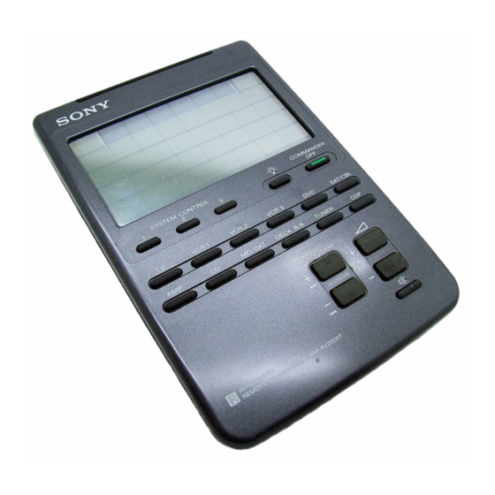
SERVICE MANUAL
MICROFILM
RM-AV2000T
SPECIFICATIONS
Operating distance
Approx. 10 meters (32.8 ft.) (varies
depending on components of different
manufacturers)
Power requirements
Remote control : Four R6 (size AA)
batteries
Backlight : Two R6 (size AA) batteries
Battery life
Apporox. 6 months (varies depending on
frequency of use)
Approx. 120 × 175 × 45 mm
Dimensions
(4
3
/
4
Mass
290g (10.22 oz.) (not including batteries)
Design and specifications are subject to change without notice.
INTEGRATED REMOTE COMMANDER
× 7 × 1
in.) (w × h × d)
13
/
16
AEP Model
UK Model
E Model
Advertisement
Table of Contents

Related Manuals for Sony RM-AV2000T


Summary of Contents for Sony RM-AV2000T
- Page 1 RM-AV2000T SERVICE MANUAL AEP Model UK Model E Model SPECIFICATIONS Operating distance Approx. 10 meters (32.8 ft.) (varies depending on components of different manufacturers) Power requirements Remote control : Four R6 (size AA) batteries Backlight : Two R6 (size AA) batteries Battery life Apporox.
-
Page 2: Table Of Contents
COMPONENTS IDENTIFIED BY MARK ! OR DOTTED LINE WITH MARK ! ON THE SCHEMATIC DIAGRAMS AND IN THE PARTS LIST ARE CRITICAL TO SAFE OPERATION. REPLACE THESE COMPONENTS WITH SONY PARTS WHOSE PART NUMBERS APPEAR AS SHOWN IN THIS MANUAL OR IN SUPPLEMENTS PUBLISHED BY SONY. -
Page 3: General
SECTION 1 This section is extracted from instruction manual. GENERAL — 3 —... - Page 4 — 4 —...
- Page 5 — 5 —...
- Page 6 — 6 —...
- Page 7 — 7 —...
- Page 8 — 8 —...
- Page 9 — 9 —...
- Page 10 — 10 —...
- Page 11 — 11 —...
- Page 12 — 12 —...
- Page 13 — 13 —...
- Page 14 — 14 —...
-
Page 15: Disassembly
SECTION 2 DISASSEMBLY Note: Follow the disassembly procedure in the numerical order given. 2-1. REMOVAL OF CASE (LOWER) Case (upper) +K2 × 8 Case (lower) Case (upper) Claw × 6 Battery lid Precision screwdriver Insert a precision screwdriver tip in between the Case (upper) and the Case (lower). -
Page 16: Test Mode
SECTION 3 TEST MODE TEST Mode (Operation Check) Preform the following operation checks using the TEST Mode before LCD touch-key block starting the repair works. COMMANDER OFF 1. All Keys Operation Check PROGRAM + Connection Method : Á + Regulated power supply (+6V constant voltage output) +6V pin –... - Page 17 2. S-RAM (Learning Function) Operation Check 3. Oscillation frequency Check Connection Method : Connection Method : MAIN board Regulated power supply PROGRAM – MAIN BOARD (CONDUCTOR SIDE) (+6V constant voltage output) Á – Regulated power supply (DV +6V constant voltage) TP GND +6V pin TP VDD...
-
Page 18: Diagrams
RM-AV2000T SECTION 4 DIAGRAMS 4-1. PRINTED WIRING BOARD – MAIN SECTION – • Semiconductor • Semiconductor Location Location Ref. No. Location Ref. No. Location Ref. No. Location B-10 Note: • X : parts extracted from the component side. ® •... -
Page 19: Schematic Diagram -Main Section
RM-AV2000T 4-2. SCHEMATIC DIAGRAM – MAIN SECTION – • See Page 23, 25 IC Pin Function. MAIN BOARD LCD1 D.SKIP Q12,13 TPELOUT MA738 MSD602 4.7k EL SWITCH 1.5k TPEL0 4.7K MSB709 (DARK) -/-- CONTINUE CLEAR SHUFFLE REPEAT MA738 ENTER TPBZ... -
Page 20: Ic Pin Functions
4-3. IC PIN FUNCTION • IC1 (µPD753017) µPD753017 is the 4-bit single-chip microprocessor for the LCD panel display with the built-in controller and driver. Pin No. Pin Name Pin Function Pin No. Pin Name Pin Function – Positive power supply terminal. 1 to 12 S12 to S23 Segment signal output terminals. - Page 21 • IC2 (µPD65012) Pin No. Pin Name Pin Function 1 to 8 ID7 to ID0 Data transfer between µPD65012 and microprocessor. IENN/IWIN 9 to11 Control input from microprocessor. IRDN. — GND terminal. 13 to 20 IP30 to IP37 Key scan input. 21 to 28 IP40 to IP47 Key scan input.
- Page 22 SECTION 5 EXPLODED VIEWS NOTE: • -XX, -X mean standardized parts, so they may • The mechanical parts with no reference number The components identified by mark ! or dotted line with mark ! are critical for safety. have some differences from the original one. in the exploded views are not supplied.
- Page 23 SECTION 6 MAIN ELECTRICAL PARTS LIST NOTE: • Due to standardization, replacements in the • RESISTORS The components identified by mark ! or parts list may be different from the parts All resistors are in ohms. dotted line with mark ! are critical for safety. specified in the diagrams or the components METAL: metal-film resistor Replace only with part number specified.
- Page 24 RM-AV2000T MAIN Ref. No. Part No. Description Remarks Ref. No. Part No. Description Remarks 1-216-097-91 RES,CHIP 100K 1/10W MISCELLANEOUS 1-216-097-91 RES,CHIP 100K 1/10W ************** 1-216-097-91 RES,CHIP 100K 1/10W 1-216-097-91 RES,CHIP 100K 1/10W 9-880-048-01 RUBBER SWITCH 1-216-097-91 RES,CHIP 100K 1/10W 9-995-521-01 COMMON TERMINAL...
Need help?
Do you have a question about the RM-AV2000T and is the answer not in the manual?
Questions and answers