Table of Contents
Advertisement
Quick Links
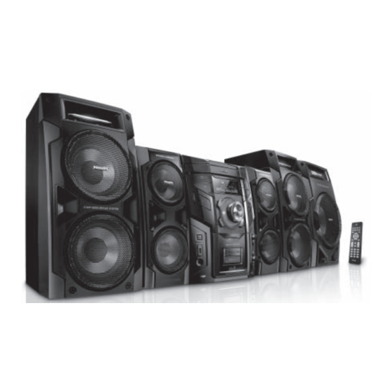
MP3 Mini Hi-Fi System
CONTENTS
Technical specification ..................................................................1-2
Service measurement setup..........................................................1-3
Service aids .................................................................................1-4
Instructions on CD playability ................................................2-1..2-2
Disassembly diagram............ ................................................3-1..3-2
Block diagram ................................................................................4-1
Wiring diagram ..............................................................................4-2
Main board
Circuit diagram ..................................................................5-1..5-2
Layout diagram ..................................................................5-3..5-4
AMP board
Circuit diagram .........................................................................6-1
Layout diagram ..................................................................6-2..6-3
Front board
Circuit diagram .........................................................................7-1
Layout diagram ..................................................................7-2..7-3
©
Copyright 2009 Philips Consumer Electronics B.V. Eindhoven, The Netherlands
All rights reserved. No part of this publication may be reproduced, stored in a retrieval
system or transmitted, in any form or by any means, electronic, mechanical, photocopying,
or otherwise without the prior permission of Philips.
Published by LX 0946 Service Audio
Version 1.0
Subject to modification
MCU board
Circuit diagram .........................................................................8-1
Layout diagram ..................................................................8-2..8-3
CD Board
Circuit diagram. ........................................................................9-1
Layout diagram ..................................................................9-2..9-3
Sub Power Board (it is not repaired,diagram for referrence only)
Circuit diagram. ......................................................................10-1
Layout diagram .......................................................................10-1
Sub AMP Board (it is not repaired,diagram for referrence only)
Layout diagram ....................................................................... 11-1
Sub SW Board (it is not repaired,diagram for referrence only)
Layout diagram .......................................................................12-1
Exploded view diagram ...............................................................13-1
Mechanical parts list ...........................................................13-2..13-3
Electrical parts list...............................................................14-1..14-2
FWM997X
/78
FWM997
/55
3141 785 33280
Advertisement
Table of Contents

Related Manuals for Philips FWM997X/78


Summary of Contents for Philips FWM997X/78
-
Page 1: Table Of Contents
Electrical parts list...............14-1..14-2 © Copyright 2009 Philips Consumer Electronics B.V. Eindhoven, The Netherlands All rights reserved. No part of this publication may be reproduced, stored in a retrieval system or transmitted, in any form or by any means, electronic, mechanical, photocopying, or otherwise without the prior permission of Philips. -
Page 2: Technical Specification
1 - 2 TECHNICAL SPECIFICATION AMPLIFIER FRONT SPEAKERS RMS output power System 4-way; double port bass reflex Impedance ............... 2 x 6 Ω Total output power ....... 800 W RMS Signal-to-noise ratio ......67 dB A (IEC) Woofer ..............2 x 5.25” Frequency response ...... - Page 3 MEASUREMENT SETUP Tuner FM Bandpass LF Voltmeter 250Hz-15kHz e.g. PM2534 e.g. 7122 707 48001 RF Generator e.g. PM5326 S/N and distortion meter e.g. Sound Technology ST1700B Use a bandpass filter to eliminate hum (50Hz, 100Hz) and disturbance from the pilottone (19kHz, 38kHz). Tuner AM (MW,LW) Bandpass LF Voltmeter...
-
Page 4: Service Aids
SERVICE AIDS WARNING All ICs and many other semi-conductors are susceptible to electrostatic discharges (ESD). Careless handling during repair can reduce life drastically. When repairing, make sure that you are connected with the same potential as the mass of the set via a wrist wrap with resistance. Keep components and tools also at this potential. -
Page 5: Instructions On Cd Playability
2 - 1 INSTRUCTIONS ON CD PLAYABILITY Customer complaint "CD related problem" Set remains closed! check playability playability ok ? For flap loaders (= access to CD drive possible) "fast" lens cleaning cleaning method is recommended check playability playability ok ? Play a CD for at least 10 minutes check playability... - Page 6 2 - 2 INSTRUCTIONS ON CD PLAYABILITY PLAYABILITY CHECK LIQUID LENS CLEANING Before touching the lens it is advised to clean the surface of the lens by blowing clean air over it. For sets which are compatible with CD-RW discs This to avoid that little particles make scratches on use CD-RW Printed Audio Disc ....7104 099 96611 the lens.
-
Page 7: Disassembly Diagram
3 - 1 3 - 1 DISASSEMBLY DIAGRAM VIEW PART 1... - Page 8 3 - 2 3 - 2 DISASSEMBLY DIAGRAM VIEW PART 2...
-
Page 9: Block Diagram
4 - 1 4 - 1 SET BLOCK DIAGRAM 3CDC CD Loader PICK-UP MECHA SANYO : DA-11VF PLL Tuner (SANYO LC72131+TA1823 or Panasonic TM10) ROHM 4 CH MOTOR DRIVER RF AMP+SSP+DSP (BA5826) (BU9543) 74VC157 CE2632 SDRAM Spectrum 16Mbit analyzers MCS LOGIC BX8800 MP3/WMA En/De + MCU +USB/CARD NOR FLASH LED controller... -
Page 10: Wiring Diagram
4 - 2 4- 2 SET WIRING DIAGRAM... - Page 11 5 - 1 5 - 1 CIRCUIT DIAGRAM - MAIN BOARD PART 1...
- Page 12 5 - 2 5 - 2 CIRCUIT DIAGARM - MAIN BOARD PART 2...
- Page 13 LAYOUT DIAGARM - MAIN BOARD MAIN BOARD COMPONENT SIDE VIEW...
- Page 14 LAYOUT DIAGARM - MAIN BOARD MAIN BOARD COPPER SIDE VIEW...
- Page 15 6 - 1 6 - 1 CIRCUIT DIAGRAM - AMP BOARD...
- Page 16 6 - 2 6 - 2 LAYOUT DIAGARM - AMP BOARD AMP BOARD COMPONENT SIDE VIEW...
- Page 17 6 -3 6 - 3 LAYOUT DIAGARM - AMP BOARD AMP BOARD COPPER SIDE VIEW...
- Page 18 7 - 1 7 - 1 CIRCUIT DIAGRAM - FRONT BOARD...
- Page 19 7 - 2 7 - 2 LAYOUT DIAGARM - FRONT BOARD COMPONENT SIDE VIEW...
- Page 20 7 - 3 7 - 3 LAYOUT DIAGARM - FRONT BOARD COPPER SIDE VIEW...
- Page 21 8 - 1 8 - 1 CIRCUIT DIAGRAM - MCU BOARD...
- Page 22 8 - 2 8 - 2 LAYOUT DIAGARM - MCU BOARD COMPONENT SIDE VIEW...
- Page 23 8 - 3 8 - 3 LAYOUT DIAGARM - MCU BOARD COPPER SIDE VIEW...
-
Page 24: Circuit Diagram
9 - 1 9 - 1 CIRCUIT DIAGRAM - CD BOARD... -
Page 25: Layout Diagram
9 - 2 9 - 2 LAYOUT DIAGRAM - CD BOARD COMPONENT SIDE VIEW... -
Page 26: Layout Diagram
9 - 3 9 - 3 LAYOUT DIAGRAM - CD BOARD COPPER SIDE VIEW... - Page 27 10 - 1 10 - 1 CIRCUIT DIAGRAM - SUB POWER BOARD LAYOUT DIAGRAM - SUB POWER BOARD (in subwoofer box) AC IN C0N602 FWM996 CN602 AC JACK CN603 SW2 A CN6/3.96 CN6/3.96 SW2 B AC27V OUT T901 F908 T5AL/250V CN5/3.96 CN5/3.96 CON601...
- Page 28 11 - 1 11 - 1 LAYOUT DIAGRAM - SUB AMP BOARD (in subwoofer box)
- Page 29 12 - 1 12 - 1 LAYOUT DIAGRAM - SUB SW BOARD (in subwoofer box)
-
Page 30: Exploded View Diagram
13 - 1 13 - 1 EXPLODED VIEW DIAGRAM... -
Page 31: Mechanical Partslist
IR LENS 996510016132 POWER LIGHT GUIDE 996510016133 VOL LIGHT GUIDE 996510016134 DBB LIGHT GUIDE 996510017820 MAX BUTTON LIGHT GUIDE 996510000439 PHILIPS LOGO 996510017821 MIDDLE STRAP SOUND BUTTON 996510020797 DISPLAY TOP BAR 996510020803 MIDDLE STRAP TOP BUTTON 996510016139 MIDDLE STRAP L 996510016140... - Page 32 13- 3 ACCESSORIES J003 ! 994000001478 AC PLUG ADAPTOR J010 996510016101 AM LOOP ANTENNA J011 996510009429 FM ANT (GREY) 1.5M CE/75 J012 996510002103 CONN. CORD 3.5 ST/PLUGx2 500mm J012 996510020804 9P MINI DIN CABLE L=1.5M BLK J110 ! 996500037714 AC CORD SET VDE/BRAZIL APP 1.8 (for -X/78) J110 994000001692...
-
Page 33: Electrical Partslist
14 - 1 ELECTRICAL PARTSLIST MAIN BOARD ASSEMBLY C927 994000001225 SAFETY CAP 275V 0.22UF -20% CN606 994000001221 V/RCA JACK 2P F902 ! 996510002426 CERAMIC FUSE 3.9x10.5mmW F904 ! 994000000586 GLASS FUSE W/LEAD 3.15A/250V IC601 996510005250 IC TDA7468D IC603 996510018852 IC UTC7808 IC606 996510018962 IC UTC7805... - Page 34 14 - 2 ELECTRICAL PARTSLIST FRONT BOARD ASSEMBLY D914 994000001234 LED LAMP 3MM (RED) D920 996510017986 LED LAMP 2x5x7mm FTD901 996510016092 VFD DISPLAY J905 996510000344 USB SOCKET J908 994000001244 V/PHONE JACK 3.5MM P901 994000000325 OPTIC SENSER (OPTO..) SW901 994000001243 TACT SWITCH U901 996510016091 IC PT6324...
Need help?
Do you have a question about the FWM997X/78 and is the answer not in the manual?
Questions and answers