Table of Contents
Advertisement
Advertisement
Table of Contents

Subscribe to Our Youtube Channel
Related Manuals for Malouf Structures E455

Summary of Contents for Malouf Structures E455
- Page 1 OWNER’S MANUAL...
- Page 2 OWNER’S MANUAL WARNINGS IMPORTANT: PLEASE READ ALL SAFETY INSTRUCTIONS THOROUGHLY BEFORE USING THIS PRODUCT. SAVE THESE INSTRUCTIONS. PACEMAKERS • Some pacemakers may detect motion by this product as a false sense of movement or exercise. This may or may BEFORE USE not affect your pacemaker.
- Page 3 RF exposure requirement and void user’s right to operate the device. POWER RATINGS • INPUT: AC 100-240V - 50/60Hz, 1.5 Amp • OUTPUT: DC 29V-2A • This•product•is•designed•to•have•no•maintenance•requirements•by•the•user.•Please•do•not•open• any•motor•compartments,•alter•the•wiring,•modify•the•base,•or•change•the•product•in•any•way•as• it•will•void•the•warranty.••• For•any•questions•or•concerns•regarding•this•product•please•contact•malouf •directly. ®...
- Page 4 OWNER’S MANUAL CONTENTS Overview 1•-•2 Assembly 3•-•10 Remote Control 11•-•14 Electrical Components and Backup Battery 15•-•20 Synchronizing Two Bases 21•-•24 Test All Functions / Additional Help 25•-•27 Warranty Information 29•-•30...
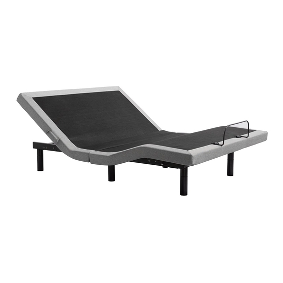
- Page 5 Head Motor Foot Motor OWNER’S MANUAL Control Box OVERVIEW USB Ports Get to Know Your Product Retainer•Bar Power Supply Box Before•beginning•assembly•of•the•Structures ™•E455•Adjustable•Base,•please• take•a•moment•to•familiarize•yourself•with•the•parts•and•location•of•components.• See•the•adjacent•image•for•a•detailed•overview. (12) 3-Inch Legs Power Cord (6) 6-Inch Legs If•any•parts•or•components•are•missing,•or•are•different•than•shown•in•the• adjacent•image,•do•not•attempt•to•complete•the•assembly•process•and•contact• (6) End Caps customer•support:•800.517.7179•/•customerservice@maloufsleep.com.•••• Wireless Remote Control (7) Leg Sets Included Sync Cable with King Size...
- Page 6 OWNER’S MANUAL ASSEMBLY Before You Begin A•minimum•of•two•people•are•required•to•assemble•this•adjustable•base. Open•box•on•the•floor•in•the•flat•position,•bottom•facing•up,•to•avoid•damage. Step 1: Place•the•box•in•the•room•the•bed•will•be•used•with•the•bottom•of•the•box•facing•up.• Carefully•remove•packaging•material,•taking•care•not•to•puncture•the•box•with•any sharp•objects.• Step 2: Remove•the•bed•base•from•the•box•and•set•mattress•(top)•side•down•on•the•floor• (see image A).•Remove•all•plastic•and•zip•ties.•All•components•and•parts•are•located• in•the•underside•of•the•base.•Remove•attached•parts•and•set•aside•in•preparation•for• assembly•(see image B).•Check•to•make•sure•all•parts•have•been•included•and•are•not• damaged•(see page 2 for a list of all parts and components). King Size Only...
- Page 7 OWNER’S MANUAL Middle•Leg•on•King•Size•Only Head ASSEMBLY Step 3: Hand•tighten•all•six•legs•(seven•for•King•size)•into•the•bed•frame•until•secure.•Note• that•there•are•two•location•options•for•each•leg,•an•outside•placement•or•an•inside• placement.•Tighten•the•legs•in•the•location•of•your•choosing,•maintaining•a•consistent• inside•or•outside•location•throughout.•Take•care•not•to•over•tighten•(see image A).• To•reach•a•15-inch•height•from•the•floor•to•the•top•of•the•deck•use•a•3-inch•+•3-inch•+• 6-inch•leg•assembly. Note: Ensure the bottom of each leg has an end cap attached (see image B). Step 4: Install•the•power•cord•by•connecting•the•cord•jack•to•the•receptacle•on•the•bed• motor•(see image C).•Be•sure•the•cord•is•connected•completely•and•securely. Foot...
- Page 8 OWNER’S MANUAL ASSEMBLY Step 5: With•two•to•four•people,•lift•the•bed•by•the•metal•frame•and•turn•it•over•so•the• mattress•(top)•side•is•facing•up•(see image A).•Take•caution•not•to•lift•the•bed•with•the• fabric,•or•to•use•the•legs•as•pivot•points•causing•angled•pressure•as•this•may•cause• damage.•Move•the•bed•to•the•desired•location.
- Page 9 OWNER’S MANUAL ASSEMBLY Step 6: To•install•the•mattress•retainer•bar,•insert•one•end•of•the•retainer•bar•in•its•respective• slot•until•it•slides•fully•into•place•(see image A).•Flex•retainer•bar•to•insert•the•other•end• on•the•other•side. Step 7: Plug•the•power•cord•into•the•wall•outlet•and•run•the•test•on•pages•25•–•26•of•this• manual.•You•may•want•to•familiarize•yourself•with•the•remote•control•functions•(pages 11 – 14)•prior•to•running•the•test.•...
- Page 10 OWNER’S MANUAL REMOTE Head•Up Foot•Up CONTROL Overview All•of•the•functions•of•the•bed•can•be•operated•with•the•remote•control.•The•remote• Foot•Down Head•Down control•comes•with•pre-programmed•buttons•that•will•automatically•adjust•when•pressed,• or•you•can•manually•control•adjustments•using•the•arrow•buttons•on•the•remote•control.• See•the•diagram•to•the•right•(see image A)•for•a•complete•list•of•remote•control•functions. Flat Remote Control Battery Installation Remove•the•battery•cover•on•the•back•side•of•the•remote•control.•Insert•the•two•included• AAA•batteries•(see image B). Preset•Zero•Gravity•Position Preset•Anti•Snore•Position or•Programmable•Position•A or•Programmable•Position•B Programmable Buttons Zero•Gravity•and•Anti•Snore•are•both•pre-programmed•positions•that•can•be•adjusted• and•saved•to•match•your•preference.•Simply•adjust•your•bed•to•the•desired•position,•then• hold•down•the•Flat•button,•then•simultaneously•press•the•position•button•you•want•to• reprogram.
- Page 11 OWNER’S MANUAL REMOTE Overview CONTROL The•original•remote•that•comes•in•the•box•is•already•paired•to•the•foundation.•No•further• PAIRING action•is•required.•In•the•event•that•the•remote•is•not•paired•with•the•base,•begin•by• checking•the•following. Step 1: Ensure•the•remote•batteries•are•functioning.•Replace•if•necessary. Step 2: Ensure•the•power•cord•is•plugged•into•a•powered•source. The•blue•pairing•button•can•also•be• used•to•lower•the•base•to•the•flat• Step 3: position•in•case•of•an•emergency (see battery backup section on Press•and•hold•the•Head•Up•and•Foot•Up•buttons•simultaneously•(see•image•A).•Then• pages 19 – 20). also•press•and•hold•the•blue•button•on•the•control•box•cord•until•you•hear•two•beeps• (see•image•B).
- Page 12 OWNER’S MANUAL ELECTRICAL COMPONENT SETUP Overview Sync•Cable•Input• The•electronic•components•are•pre-installed•and•no•assembly•is•necessary;• (see pages 23–24) however,•some•input•locations•are•important•for•proper•setup•and• Head•Motor•Input USB•Input•1 functionality•(see images A and B to become familiar with input, setting and part locations). Foot•Motor•Input USB•Input•2...
- Page 13 OWNER’S MANUAL ELECTRICAL COMPONENT SETUP USB Ports USB•ports•are•located•under•the•head•portion•of•the•bed•base•at•two•locations• (see image A).•To•access•the•USB•ports,•press•the•Head•Up•button•to•raise•the• bed•and•reveal•the•USB•ports.•Once•your•device•is•plugged•into•the•USB•port,• you•may•lower•or•adjust•the•bed•to•your•preference. NOTE: USB ports are for charging output only.
- Page 14 OWNER’S MANUAL BACKUP Overview BATTERY Important: The backup battery is only to be used in case of a power outage. Batteries are not to be used for normal operation of the bed. The backup battery will not support repeated movement for an extended period of time. Backup Battery Use Use•two•9V•batteries•only•(not•included).•If•a•power•outage•occurs,•install•the•...
- Page 15 OWNER’S MANUAL OPTION 1: WIRELESS SYNCHRONIZING TWO BASES Pair Single Remote to Operate Two Bases Simultaneously (for Twin XL and split sizes only) Step 1: Ensure•both•bases•(A•and•B)•are• plugged•into•a•power•source. Step 2: Make•sure•Remote•A•was•already• paired•to•Base•A•and•Remote•B•was• paired•to•Base•B.•If•not,•pair•them•by• following•the•instructions•found•on• pages•13•–•14. Step 3: After•remotes•are•paired•to•their• respective•bases,•pair•Remote•A•to• Base•B•(see pages 13 – 14).•Both•bases• can•now•be•operated•by•Remote•A.
- Page 16 OWNER’S MANUAL SYNCHRONIZING TWO BASES (for Twin XL and OPTION 2: WIRED split sizes only) Step 1: Place•two•Twin•XL•or•split•size•adjustable•bases•next•to•each•other•in•desired• location. Plug•in•Sync•Cable•(see image A)•to•the•control•box•of•each•base•into• the•“Program”•input•(see image B) on•the•control•box.• Step 2: With•the•connecting•cable•installed,•use•remote•and•test•all•functions•of•the•bed• base•(see pages 25-26). If•remotes•are•not•working,•troubleshoot•the•problem•by• following•the•instructions•on (pages 13-14). The•two•bases•are•now•connected•and•ready•for•normal•use.
- Page 17 OWNER’S MANUAL TEST ALL FUNCTIONS Head•Up Head•Down Foot•Up Foot•Down Flat Overview Zero•Gravity To•ensure•proper•setup,•use•remote•and•test•all•functions•for•3•seconds. Anti•Snore Important: Always return the base to the flat position when switching between preset options.
- Page 18 OWNER’S MANUAL NOTES: ADDITIONAL If one or more functions of the bed have stopped working: HELP Check•under•the•bed•base•to•verify•the•wired•connections•are•secure•and•there• are•no•cords•or•bedding•obstructing•the•movement•of•the•base. The remote control won’t operate the bed functions: Make•sure•the•batteries•are•installed•correctly•or•install•two•new•AAA•batteries•into• the•remote•control.•Ensure•the•remote•control•is•synced•with•the•control•box•on•the• bed•(see pages 13 – 14). No functions of the bed will operate: Check•to•ensure•the•power•cord•is•properly•connected.
- Page 19 YEARS 2 – 5: dealing, custom, trade, or otherwise. Malouf® shall not be liable for any consequential damages or losses arising from the During the years 2 – 5 from the date of purchase, Malouf® will offer replacement parts for purchase, installation and/or use of this product.
Need help?
Do you have a question about the Structures E455 and is the answer not in the manual?
Questions and answers