Table of Contents
Advertisement
Quick Links
StEin
Stationary Equipment Module
StEin -
INSTRUCTION MANUAL
short for
StEin
(= Stationary-Equipment) - Module
and
StEin expansion boards
Note: A separate instruction manual
will cover the external ICA boards
2
(via I
C bus).
Page 1
EDITION
Preliminary Edition
2017 12 18
2018 01 02
2018 02 06
2018 05 13
1018 06 11
2018 06 19
2018 06 27
2018 07 20
2018 08 21
2018 10 20
2018 11 10
2018 11 30
2018 12 05
2018 12 15
2019 02 14
Advertisement
Table of Contents

Subscribe to Our Youtube Channel
Related Manuals for ZIMO StEin


Summary of Contents for ZIMO StEin
- Page 1 2018 10 20 2018 11 10 2018 11 30 StEin 2018 12 05 2018 12 15 (= Stationary-Equipment) - Module 2019 02 14 StEin expansion boards Note: A separate instruction manual will cover the external ICA boards (via I C bus).
-
Page 2: Table Of Contents
Chapter Page Product features and system configurations ................4 1. Setup technical data, “StEin” configuration-strategy ............... 6 2. Self-Update and Loading conf., sound and other data ............11 3. The “button-procedures” for “manual operation” ..............12 4. Monitoring and operating with the MX32 ................14 5. - Page 3 This page is under construction SOFTWARE and SOFTWARE-UPDATES: To learn more about the current software version and to download a free copy, go to the ZIMO website www.zimo.at and click on the tab “Update & Software” (“Update – System”). General information: ...
-
Page 4: Product Features And System Configurations
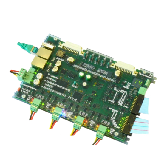
The "StEin" is equipped with a numeric display (for displaying the module number and as A special feature of the "StEin"-concept is the origin of the DCC signal at the track out- support for manual setup) as well as numerous control LEDs: occupancy status, short cir- puts: "StEin"... - Page 5 (Track voltage “N” or the MX10 output “N”. from this the StEin produces the DCC signal for the track outputs Up to 16 ICA boards 1 … 8, the same way as the MX10 does for the “Schiene 1” output per “StEin”...
-
Page 6: Setup Technical Data, "Stein" Configuration-Strategy
StEin Page 6 Stationary Equipment Module , “StEin” configuration-strategy “StEin” data model 1. Setup technical data CAN-Bus Control-LED: Green flashing 1 Hz = up to 25/sec messages 2 Hz = up to 100/sec received Buttons and LED indicators for local... - Page 7 The goal of these settings and procedures is that only the one track section is turned off, on which an overcurrent or short circuit occurs. On the other hand, it would be wrong, if the supply of the running voltage from the MX10 (to which the StEin modules are connected) would be turned off entirely in case Others: of an overcurrent or short circuit on a track section.
- Page 8 8 track outputs of the StEin is used for an identically configured section, among them is always (at least) the object’s connection point at the StEin; in the case of a the APUGA column (track section connection point; some center columns are missing in this illustration turnout, the turnout output number, which by the way does not necessarily have to be at to make the APUGA column visible) contains entries such as M.3, where "M"...
- Page 9 StEin module; each module only picks the proper lines (according to the parameter MODULNR). An example is shown here of a parameter sheet that contains object lines for multiple StEin modules. For easier identification we added the additional column MODULNR to the usual col-...
- Page 10 T h e “S t E i n” D a t a m o d e l Non-volatile memory Loading the into the StEin: Configurations StEin’s Active The list of the object lines for the StEin Active .cfg USB socket file configuration in Module is called parameter sheet.
-
Page 11: Self-Update And Loading Conf., Sound And Other Data
Plugging in the flash drive StEin on the drive; the second sign (in this case “b”) = the type of the first file. This means: the first sign (in this case “4”) = the number of files for the “b”... -
Page 12: The "Button-Procedures" For "Manual Operation
- see next chapter), turnouts connected to the StEin can be tested, as well as track sections set to H - L - U - etc. while observing Confirm with Button-2 occupancy threshold for track section outputs are the effect on locomotives, even without a cab or a computer. - Page 13 StEin Stationary Equipment Module Page 13 How to operate single LED’s on signal boards: How to restore power after a short circuit/overcurrent: Start with the module in its normal operating state (Address displayed), i.e.: Start with the module in its normal operating state (Address displayed), i.e.: (Button-2 ...
-
Page 14: Monitoring And Operating With The Mx32
- press the corresponding number key Switches the turnout back and forth. IN - Switch inputs: for each of the 16 switch inputs - the current state (green dot means: ON). (Shift)- Software of ALL StEin modules is shown in the list; (to get a rough idea) -
Page 15: The 8 Track Sections, Overcurrent And Short Circuits
Cables wired in parallel can provoke capacitive or inductive crosstalk, rail is normally not sectioned off and is therefore continuous; the “N” pins on the StEin concerning data in forward direction (DCC signal, HLU information) as well as feedback are internally connected in parallel;... - Page 16 “real” short circuit, in which case an immediate shut-down is essential, due to jeopardizing ve- The 8 track section outputs of the StEin can take on different states individually, which are repre- hicles and track material (and if set to 8A also the module itself is in danger); therefore, there is NO ad- sented by the LEDs next to the clamps, but are also sent to controllers and computer (interlocking justable turn-off time;...
- Page 17 StEin Stationary Equipment Module Page 17 Overcurrent threshold UESLAMP Power is restored after UESLEZT Power turns off after UESLAZT According to UESLEAZ (quantity i.e. 5), Overcurrent conditions (current via UESLAMP, i.e. 1.5 expires (“long” overcurrent time, “long” overcurrent threshold is expires (long reset time, i.e.
-
Page 18: Track Sections, Point Detectors, Point Following Commands
The purpose of the point detectors is to switch the track section from one HLU step to another as soon as a train is detected; for example from L to H, displayed: L/H. One StEin module has (inter alia) 8 outputs for track sections and 16 logic level inputs. Those inputs are used for point detectors , whereby less track sections are needed Point detectors are used in two situations;... -
Page 19: Terminal Loops
StEin Stationary Equipment Module Page 19 Terminal loops Terminal loop sections are built by two tracks sections next to each other (each con- nected with a 3-pole plug). …………………………….. PRELIMINARY TEXT: Switching terminal loops - new strategy At terminal loops both outputs are connected inversely,... -
Page 20: The 8 Outputs For8 Turnouts / 16 Single Consumers
“5-LED-group”. Thereby, it is irrelevant what triggers the switching: operation on the module itself by the key procedure "4" (turnouts, also "automatic cleaning"), or from the controller (StEin LIST) or an interlocking program. The left LED-pair (= the two left LEDs) are assigned to one turnout and the right-LED pair to another. -
Page 21: The Speaker Outputs Of The Stein
StEin Stationary Equipment Module Page 21 The speaker outputs of the StEin WILL BE ADDED LATER The Signal Boards at the I C Bus WILL BE ADDED LATER The Track Section Expansion Boards WILL BE ADDED LATER The Turnout Expansion Boards... -
Page 22: Prepared Configurations And Their Activation
... it is very easy to initially configure the "StEin" with the help of the “prepared con- and then modify for the individual purpose, etc. - Page 23 StEin Stationary Equipment Module Page 23 etc. - all objects of the prepared configurations as objects “track sections” and “double-way turnout”...
-
Page 24: Description Of The Objects In The Parameter Sheets
"StEin" module via a flash drive as exported parameter sheets. See chapter “Setup, technical data, “StEin” configuration-strategy” Parameter sheets can contain objects for one, several (or all) "StEin" modules: the re- spective module selects its "own" objects and only loads those parameters into its own memory. - Page 25 Hier kann eingetragen werden, in wel- wenn Objektzeile (laut OBJKL, siehe = GATYP Kennzeichen für ein eingetragen werden, der KEINE chem der eingesetzten StEin-Module links) der Objektklasse GATYP = 1 ... 65000: jede Nummer darf system- Objekt der Objektklasse Wirkung im Betrieb hat, sondern (laut der am Display angezeigten Num- weit (also für die gesamte Anlage) nur...
- Page 26 ZIMO Systemen (MX1, MX9, ...), z.B. 35.2. Modul für einen Vorabschnitt für z.B. 35.13 z.B. 35.7 wo die Gleisabschnitte des StEin- Gleiseinfahrten, z.B. 49.3 Modul-Nummer = 1 ... 65000 Modul-Nummer = 1 ... 65000 Modul-Nummer = 1 ... 65000 Moduls MX9-Module simulieren.
- Page 27 ZIMO Systemen (MX1, MX9, ...), z.B. 35.2. Modul für einen Vorabschnitt für z.B. 35.13 z.B. 35.7 wo die Gleisabschnitte des StEin- Gleiseinfahrten, z.B. 49.3 Modul-Nummer = 1 ... 65000 Modul-Nummer = 1 ... 65000 Modul-Nummer = 1 ... 65000 Moduls MX9-Module simulieren.
- Page 28 StEin Page 28 Stationary Equipment Module Table excerpt “WEITYP”, the templates for turnouts Table excerpt “WEI”, the list of actual turnouts WEITYP WEITYP WEITYP WEITYP...
- Page 29 StEin Stationary Equipment Module Page 29 Table excerpt “SIGTYP”, the signal template Table excerpt SIG, i.e. the list of actual signals, which are based on the templates SIGTYP and SIGBILD.
- Page 30 StEin Page 30 Stationary Equipment Module This is a preliminary excerpt of the planned signal types Table excerpt “SIGBILD” as template for the signal aspects in the table “SIG”...
-
Page 31: Configuration Example (Zimo N-Scale Show Layout)
The ZIMO N-scale layout is built on an area of 2 x 1.3 m. The track is mounted directly on acrylic glass. Since it is a demonstration layout, all (StEin-) modules along with the wiring are openly installed so they are visible. - Page 32 The turnout and coupler drives are connected to 3 (of the 8) Stein modules; this is also a two routes at the same time. This means that there are several track sections, which contribution to clarity.
- Page 33 “old” technology to the StEin). For each of the 8 StEin modules, the sheet contains an object line of the class GATYP ( = a track section type with the designation "GAZIMEN18"), which contains the parameters for the 8 individual track sections to be defined, which in this case are always the same.
- Page 34 StEin Page 34 Stationary Equipment Module...
-
Page 35: Appendix: Glossary
Note: In model railroad literature, especially in documents of other manufacturers, this combination of turnouts is often referred to as routes, but ZIMO uses the term route for a more evolved set-up: a turn- out ladder that includes track section control (a feature most often not available from other sources, so...
Need help?
Do you have a question about the StEin and is the answer not in the manual?
Questions and answers