Table of Contents
Advertisement
Quick Links
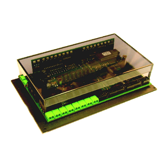
Track section module MX9
INSTRUCTION MANUAL
TRACK SECTION MODULE
plus
Plug-in boards MX9ALA, MX9AZN, MX9ASE
and
Display module MX9ZIA
MX9V
Page 1
SW-Version 3.10: several improvements for use with STP software (Operating mode 3)
and: module-autonomous applications (Operating mode 1), part one, CV # 21 28 = 141, 142 ... 149 2006 03 02
ATTENTION: when updating to version 3.03 or higher a HARD RESET must be performed by
programming CV #1 = 0!
CHAPTER
0.
About this manual .......................................................................................................................................2
1. Introduction .............................................................................................................................................................2
2. Technical Information..............................................................................................................................................3
3. Connecting the MX9 to track power and CAN bus..................................................................................................4
4. Addressing and programming the MX9...................................................................................................................5
5. Connecting external occupancy indicators and signals...........................................................................................6
6. Connecting external switch inputs ..........................................................................................................................7
7. Loco number recognition and display .....................................................................................................................7
8. OPERATING MODE 0 (zero)..................................................................................................................................8
9. OPERATING MODE 1 ............................................................................................................................................9
10. OPERATING MODE 2 ........................................................................................................................................13
11. OPERATING MODE 3 ........................................................................................................................................16
12. Replacing the EPROM........................................................................................................................................20
detection ..........................................................................................20
14. MX9 modifications for MX9ASE applications ......................................................................................................21
15. Glossary..............................................................................................................................................................21
IMPORTANT NOTES TO SOFTWARE AND SOFTWARE UPDATES:
This product contains an EPROM which stores the software that determines its
characteristics and functions.
The current software version may not contain all the functions mentioned in this manual.
Such missing functions can be "installed" and possible software glitches corrected later by
replacing the EPROM. The ZIMO website at
sions.
New EPROM's can be ordered from ZIMO. The software itself is free but a small fee applies
for the new hardware (EPROM) and shipping & handling.
EDITION
Old issues (old format)
up to 2004 07 15
2006 02 15
2006 04 20
2007 08 16
.
www.zimo.at
lists current and new software ver-
MX9ZIAP
Advertisement
Table of Contents

Subscribe to Our Youtube Channel
Related Manuals for ZIMO MX9V


Summary of Contents for ZIMO MX9V
-
Page 1: Table Of Contents
EPROM. The ZIMO website at www.zimo.at lists current and new software ver- sions. New EPROM’s can be ordered from ZIMO. The software itself is free but a small fee applies for the new hardware (EPROM) and shipping & handling. MX9ZIAP... -
Page 2: Introduction
CAN bus. Equally, signals and occupancy indicators can be connected to the MX9 as well as ZIMO term for speed limit applications F = full speed (no speed limit applied), L = low speed, U the loco number identification and display utilized in all operating modes. For this reason, the follow-... -
Page 3: Technical Information
Page 3 TECHNICAL INFORMATION: 2. Technical Information Operating voltage (from output “SCHIENE” at ZIMO command station)....12 - 24 V CAN bus voltage…………………………………………………………………………..12 - 40 V Max. current at each track output (short circuit cut-off)…………………………………..3 - 4 A *) The main board of the MX9, including the sockets for the plug-in boards, are mounted on a sturdy Allowable maximum current of all outputs……………………………………………………..8 A... -
Page 4: Connecting The Mx9 To Track Power And Can Bus
Once each module (MX9 track section modules, MX8 accessory modules and also be ordered from ZIMO with part number 6POLWID. possibly other modules) is programmed with its own unique address, it can be... -
Page 5: Addressing And Programming The Mx9
Track section module MX9 Page 5 Addressing and programming the MX9 ASSIGNING AN ADDRESS TO A MX9 MODULE: Each MX9 requires its own address, which is used to access the track sections connected to it. Assigning an address to (and often programming) a MX9 is necessary for ALL operating modes. Each address must be unique, meaning the same address cannot be used for another MX9. -
Page 6: Connecting External Occupancy Indicators And Signals
Page 6 Track section module MX9 LIGHT OUTPUT ASSIGNMENTS, if not defined differently . . . : Connecting external occupancy indicators and The occupancy indicator output pins are directly connected with the 16 track sections (sub-sections). signals See drawing below. The signal outputs are intended for block signals of the 8 main sections and will show “stop”... -
Page 7: Connecting External Switch Inputs
MX9ALA boards on the other hand can be installed at any time This modification is performed by ZIMO on request (additional internal conductors from the processor to the plug-in sockets, which are not present on the printed circuit board), even after the modules have been delivered. -
Page 8: Operating Mode 0 (Zero)
Ones digit: speed limit in defined direction of signal after power-up corre- protected block when signal is “green” (F). sponds to ZIMO speed limit codes: “33”, Main section 1 0 - 7 / Value 0= „H“ (Halt or stop) which... -
Page 9: Operating Mode 1
The linguistic use of these expressions is neither entirely consistent in the field of model railroading Main section 5 Identical for nor inside the ZIMO documentations; see “Glossary” at the end of this manual ! Main section 6 Main section 7... - Page 10 Page 10 Track section module MX9 Values for CV’s #21 … 28 in OPERATING MODE 1 (“module-autonomous applications”) The properties of each main section in operating mode 1 is determined by a corresponding CV. For example, CV #21 for main section 1, CV #22 for main section 2 etc. A ->...
- Page 11 Track section module MX9 Page 11 APPLICATION EXAMPLE – APPLICATION EXAMPLE – Manually operated unidirectional signal influenced block (“Stop in front of a red signal”) Manually operated bidirectional signal influenced block (“Stop in front of a red signal”) This represents the simplest case within the scope of the “module-autonomous applications”: the two Operation is similar as in the previous example except that trains can enter from either direction and sections of one MX9 main section are assigned to one signal;...
- Page 12 Page 12 Track section module MX9 APPLICATION EXAMPLE – APPLICATION EXAMPLE – Module-autonomous block control Module autonomous staging yard This block in detail looks as follows: In contrast to the previous examples, here the main sections of the MX9 are linked to each other. The status of a signal influenced block (whether it is set to “stop”...
-
Page 13: Operating Mode 2
Track section module MX9 Page 13 10. OPERATING MODE 2 Name Range Default Description # 12 Main section 3 for each of the 8 main sections of the MX9. # 13 Main section 4 SYSTEM-AUTONOMOUS APPLICATIONS # 14 Main section 5 Identical for # 15 Main section 6... - Page 14 Page 14 Track section module MX9 “SYSTEM-AUTONOMOUS BLOCK CONTROL” – Defining an “unidentified line” STEP BY STEP EXAMPLE OF THE DEFINITION PROCESS: The term “unidentified” indicates that the lines defined as such are not stored with a corresponding Before starting the loco, all track sections to be defined have to be unoccupied. The loco used for this address.
- Page 15 Track section module MX9 Page 15 section, not only is this second sub section set to H but the first sub section as well. This is needed in order to get a train stopped in front of a red signal where the engine is at the back, as in a push- pull operation, or with a helper engine at the end of a train.
-
Page 16: Operating Mode 3
Page 16 Track section module MX9 Name Range Default Description 11. OPERATING MODE 3 # 12 Main section 3 for each of the 8 main sections of the MX9. # 13 Main section 4 # 14 Main section 5 Identical for # 15 Main section 6 MX9 under COMPUTER control... - Page 17 Block 4 Block 1 Block 2 Block 3 Please note the terminology used to indicate section functions by Zimo and STP: F = Full speed, L = Low speed, U = Ultra low speed, H = Halt (Stop), A = Auto power off.
- Page 18 Page 18 Track section module MX9 The drawing below once again shows one of many possible ways to connect a MX9 to the layout. CAN bus Track power bus This time only one MX9 is shown that is connected to blocks with an uneven number of track sec- tions.
- Page 19 Track section module MX9 Page 19 • The two subsections of a MX9 main section can be connected to track sections that will need the routes should not overlap each other, if such parallel movements are desired. In some cases a sec- tion may consist of just one turnout.
-
Page 20: Replacing The Eprom
Page 20 Track section module MX9 13. Increasing the threshold for occupancy 12. Replacing the EPROM detection After powering down the system or disconnecting the MX9 remove the 3 Phillips screws holding the In some cases it may be necessary to increase the threshold of occupancy detection for selected Plexiglas cover (some versions only use the two front screws to hold the cover in place). -
Page 21: Mx9 Modifications For Mx9Ase Applications
Is an international standard for the secure data transfer between electronic modules and control ATTENTION: units. It is used in the automotive industry, among others. ZIMO is using this protocol via the cables the MX9 module must be modified before MX9ASE plug-in boards can be installed and switches used as input (CAN bus cable) connecting the command station with the cabs, accessory modules, track section signals. - Page 22 Page 22 Track section module MX9...
Need help?
Do you have a question about the MX9V and is the answer not in the manual?
Questions and answers