Table of Contents
Advertisement
Quick Links
User Manual
Chirascan CCD Emission Fluorometer
Applied Photophysics, Inc.
Applied Photophysics Limited
100 Cummings Center
21 Mole Business Park
Suite 440-C
Leatherhead
Beverly
Surrey
MA 01915
KT22 7BA
United States
United Kingdom
Tel: +1 978 473 7477
Tel: +44 1372 386 537
Email: info.usa@photophysics.com
Fax: +44 1372 386 477
Email: info@photophysics.com
www.photophysics.com
Advertisement
Table of Contents

Related Manuals for Applied Photophysics Chirascan CCD

Summary of Contents for Applied Photophysics Chirascan CCD
- Page 1 User Manual Chirascan CCD Emission Fluorometer Applied Photophysics, Inc. Applied Photophysics Limited 100 Cummings Center 21 Mole Business Park Suite 440-C Leatherhead Beverly Surrey MA 01915 KT22 7BA United States United Kingdom Tel: +1 978 473 7477 Tel: +44 1372 386 537 Email: info.usa@photophysics.com...
- Page 2 Chirascan CCD Emission Fluorometer This document contains important safety information. Read this document, the Chirascan V100 Spectrometer User Manual and the User Manual provided by Ocean Optics before attempting to install or use the CCD Emission Fluorometer. Failure to do so could result in death or serious injury.
-
Page 3: Table Of Contents
CONTENTS CONTENTS ................................ 3 USE OF THIS DOCUMENT ..........................4 ESSENTIAL SAFETY INFORMATION ....................... 5 CHIRASCAN CCD EMISSION FLUOROMETER INSTALLATION AND OPERATIONAL REQUIREMENTS .. 6 GLOSSARY ................................ 7 1 INTRODUCTION ............................. 8 2 INSTALLATION ............................... 9 2.1 Single Cell Peltier Temperature Controller ................... 9 2.2 6-cell Peltier Cell Holder ........................ -
Page 4: Use Of This Document
Single Cell Peltier Temperature Controller, or the 6-cell Peltier Cell Holder. It is assumed that the user of this document is familiar with the operation of the Chirascan spectrometer, and with Applied Photophysics Pro- Data software. In particular it is assumed that the user is familiar with the hazards associated with the operation... -
Page 5: Essential Safety Information
MAKE SURE THAT YOU HAVE READ AND UNDERSTOOD ALL THE SAFETY INFORMATION CONTAINED IN THE MAIN CHIRASCAN USER MANUAL AND THE USER MANUAL PROVIDED BY OCEAN OPTICS BEFORE ATTEMPTING TO INSTALL OR OPERATE THE CHIRASCAN CCD EMISSION FLUOROMETER. IF YOU HAVE ANY QUESTIONS REGARDING THE OPERATION OF THE FLUOROMETER, PLEASE CONTACT APPLIED PHOTOPHYSICS TECHNICAL SUPPORT AT THE ADDRESS SHOWN ON THE FIRST PAGE OF THIS DOCUMENT. -
Page 6: Chirascan Ccd Emission Fluorometer Installation And Operational Requirements
Servicing of the Chirascan CCD Emission Fluorometer should only be undertaken by qualified personnel. If you are in any doubt at all please contact the Applied Photophysics’ Technical Support at the address given on the front of this User Manual. -
Page 7: Glossary
Chirascan CCD Emission Fluorometer GLOSSARY The following abbreviations may be found in this User Manual Applied Photophysics Limited charge-coupled device circular dichroism infrared sample handling unit ultraviolet HYPERLINKS This document contains hyperlinks between references (for example the Contents tables, or references to Sections or Figures in the text), and sources. -
Page 8: Introduction
Chirascan CCD Emission Fluorometer 1 INTRODUCTION The Chirascan CCD Emission Fluorometer is designed to be used with a Chirascan V100 Spectrometer and the Single Cell Peltier Temperature Controller or the 6-cell Peltier Cell Holder. The detector is shown in Figure 1.1, with fitting for connecting to a Single Cell Peltier Temperature Controller. -
Page 9: Installation
Chirascan CCD Emission Fluorometer 2 INSTALLATION 2.1 Single Cell Peltier Temperature Controller The fittings required for connecting the Emission Fluorometer to the Single Cell Peltier Temperature Controller are shown in Figure 2.1. Figure 2.1: the fittings required for connection to the single cell accessory,... - Page 10 Chirascan CCD Emission Fluorometer Light guide Grommet Light guide collar Light guide ferrule Figure 2.3: light guide collar with the light guide inserted. Now insert the tip of the light guide through the grommet on the guide collar; the guide tip should protrude about 3 cm through the grommet.
-
Page 11: 6-Cell Peltier Cell Holder
Chirascan CCD Emission Fluorometer M3 nut Figure 2.5: the light guide mounted on the Single Cell Peltier Controller 2.2 6-cell Peltier Cell Holder The lens holder for the 6-cell Peltier cell holder accessory is shown in Figure 2.6. Alignment hole Knurled ring Figure 2.6: the lens holder for the 6-cell accessory... - Page 12 Chirascan CCD Emission Fluorometer Light guide Lens holder Light guide collar Figure 2.7: light guide fitted with the lens holder and light guide collar The light guide collar mounts in the fluorescence port of the Chirascan sample handling unit as in Figure 2.7.
-
Page 13: The Ccd Spectrometer
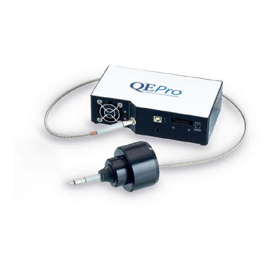
Chirascan CCD Emission Fluorometer 2.3 The CCD spectrometer The CCD spectrometer has connections for the light guide, a cable to the 5 volt DC power supply, and a USB cable to the computer. These are shown in Figure 2.9. USB cable... -
Page 14: Operation
Chirascan CCD Emission Fluorometer 3 OPERATION 3.1 Typical use The CCD Emission Fluorometer is used to measure the fluorescence emission spectrum of a sample at a set excitation wavelength or wavelengths. The total acquisition time for a reasonable spectrum is usually of the order of seconds or less, so although the spectrum is acquired sequentially with the CD, ORD or other spectrum, rather than simultaneously, only very little additional time is required. -
Page 15: Operation With Other Signals
Chirascan CCD Emission Fluorometer The conditions for the CCD are set on the Signal panel: • Integration Time: sampling time for each wavelength scan; the longer the sampling time the better the data quality, but note that there is a delay time of one second before the acquisition of the first... - Page 16 Chirascan CCD Emission Fluorometer Figure 3.3: the Mini-spectrometer dialog box. Integration Time, Scans to average and Boxcar width are described in Section 3.2.1. • ExWavelength: the excitation wavelength set on the Chirascan monochromator for the fluorescence measurements; more than one wavelength can be set, in which case the fluorescence spectra will be acquired in the order in which the wavelengths are listed.
-
Page 17: Acquiring A Baseline
Chirascan CCD Emission Fluorometer 3.2.3 Acquiring a baseline When a fluorescence spectrum is measured on the CCD, the result will be offset from zero and will appear to be a bit noisy. This can be corrected for by acquiring a baseline spectrum on the CCD with no light. This provides a baseline which can be subtracted from the sample fluorescence spectrum. -
Page 18: Example: Quinine Sulfate Reference
Chirascan CCD Emission Fluorometer 3.3.2 Example: quinine sulfate reference The CCD fluorescence spectrum of a standard sample of 1 g/ml quinine sulfate from Starna Scientific Ltd., is shown in Figure 3.5, before and after baseline subtraction. The conditions used are shown in Table 3.1. -
Page 19: Example: Anthracene Reference
Chirascan CCD Emission Fluorometer 3.3.3 Example: anthracene reference The fluorescence spectrum of a standard sample of anthracence from Starna Scientific Ltd., is shown in Figure before and after baseline subtraction. The conditions used are shown in Table 3.2. Sample spectrum... -
Page 20: Example: -Chymotrypsin
Chirascan CCD Emission Fluorometer 3.3.4 Example: -chymotrypsin show the temperature ramp CD and CCD fluorescence spectra respectively for - Figure and Figure chymotrypsin. The conditions used are given in Table 3.3. Figure 3.7: CD temperature ramp data for -chymotrypsin; the arrow shows the direction of increasing temperature Figure 3.8: CCD fluorescence temperature ramp data for -chymotrypsin after baseline correction;... - Page 21 Chirascan CCD Emission Fluorometer -chymotrypsin Sample Concentration 0.1 mg/ml Buffer citrate pH 7 25 to 80⁰C Temperature range 0.5⁰C per minute Temperature ramp rate Number of spectra Cell pathlength 2 mm CD wavelength range 250 to 190 nm CD wavelength step...
-
Page 22: Maintenance And Storage
Chirascan CCD Emission Fluorometer 4 MAINTENANCE AND STORAGE The light guide and CCD spectrometer should be maintained and stored according to the instructions provided by Ocean Optics. Document 4207Q277 V3.00 January 2018 Page 22 of 22...
Need help?
Do you have a question about the Chirascan CCD and is the answer not in the manual?
Questions and answers