Table of Contents
Advertisement
Advertisement
Table of Contents

Related Manuals for tell GPRS Pager 3


Summary of Contents for tell GPRS Pager 3
- Page 1 GPRS Pager 3 INSTALATION AND USER MANUAL...
-
Page 2: Table Of Contents
Table of contents 1 Main functions of the GPRS Pager3................3 2 Operating mode, installation..................3 2.1 Installation if no local network is available ............3 2.2 Instalation in local network / router configuration ..........4 3 Safety Reserve mode ....................4 3.1 Setup „GPRS_COM.exe” ...................5 4 Monitoring software settings..................6 4.1 Setting serial port connection................6 4.2 Event code settings.....................6... -
Page 3: Main Functions Of The Gprs Pager3
1 Main functions of the GPRS Pager3 The GPRS Pager3 can be used as an optional transmission module for alarm control panels, as well as an individual 4 zone GPRS alarm control panel. Further functions: • Sending SMS with adjustable text for each event •... -
Page 4: Instalation In Local Network / Router Configuration
In this mode GPRS Pager's signals are transfered through internet from GPRS station to the TELL Backup server, then to the monitoring station's router. The router forwards the signals to the Backup PC which makes the adequate transformations and transfers the datas to the monitoring station client PC through serial port. -
Page 5: Setup „Gprs_Com.exe
3.1 Setup „GPRS_COM.exe” • Start software „GPRS_COM.exe” (found on CD enclosed) • Connect Backup PC and Monitoring station client PC with serial Null-modem cable • Enter WEB password. The password has to be entered only at first start. • Select the physical serial port (where the cable has been connected) and open it in GPRS_COM.exe program •... -
Page 6: Monitoring Software Settings
4 Monitoring software settings 4.1 Setting serial port connection In the monitoring program serial connection should be set as follows: • Baud Rate: 9600 • Databits: • Parity: None • Stopbits: E.g. in Alarm-Sys program: 4.2 Event code settings The following event is generated by the GPRS Server, but transferred with the user ID set in the GPRS Pager: Contact-ID code Event... -
Page 7: Gprs Pager3 Setup
5 GPRS Pager3 setup For setting the GPRS Pager3 a PC is necessary with Windows operating system (Windows XP recommended) and the two programming softwares found on the CD enclosed: • GPRS_Setup.exe: for server parameter settings through USB or internet/GPRS •... -
Page 8: Setting Server Parameters Using Internet/Gprs Connection
5.1.2 Setting server parameters using internet/GPRS connection • Start „GPRS_Setup.exe” program (found on CD enclosed) • Language can be selected by clicking on the middle cell of the row on the bottom of the window (Magyar / English) • Enter the module's serial number in the second cell of "Serial nr." row (found in the framed part of the label on the back of the module) •... -
Page 9: Server Parameter Setting Details
IP address supplied by the internet provider) • Select „APN1” • Set „Port” 3333 „1. Reserve Server IP”: • Set reserve server IP address 193.28.86.102 (this is the TELL test server IP address) • Select „APN1” • Set „Port” 3333 •... -
Page 10: Setting Parameters Using Internet/Gprs Connection
6.2 Setting parameters using internet/GPRS connection • Start „GPRS Pager3” remoter software • Enter the server’s IP address and the module’s serial number • Press „Setup Login Password” button • Enter the password of WEB connection • Press „Open IP connection” button to establish connection •... -
Page 11: Monitoring Module Status
6.4 Monitoring module status • Z1, Z2, Z3 and Z4: the actual state of the four inputs is displayed here: open or closed, respectively if this is the normal state or not (according to settings). • REAY 1 and RELAY 2: actual state of relay outputs, relays can be activated by pressing "Start"... -
Page 12: Power Supply Voltage Supervision
Signs indicated in columns G1-G6, S1-S4 and C1-C2: ? - signal processing in progress * - signal transmission successful R - signal already transfered in other way, therefore signalling is not necessary ! - signal transmission failed S - alarming has been stopped, therefore signalling is not necessary T - signalling timeout If you keep the mouse pointer above any cell of the table, details of the specific event will be displayed. -
Page 13: Module Parameter Settings
6.6 Module parameter settings By pressing „Set module parameters” button the following window apears: Here saved settings can be loaded from files, saved to files or loaded to or from the module or can be compared. 6.7 Edit parameters By pressing „Edit parameters” button you will have possibility to setup the zones, events, relay outputs, telephone numbers and other parameters according to the instructions in the following chapters. -
Page 14: Zone Settings
6.7.1 Zone settings Normally open / Normally closed: you can select the active state of the zone Zone sensitivity: value in tenth seconds, slower state changes on zone inputs are ignored by the module. Entry delay: (value in seconds, 0-254): This is the time left to disarm the module after violating the specific zone, otherwise at expiration the alarm process is started. -
Page 15: Event Settings
6.7.2 Event settings Contact-ID code: event code of 3 digits containing 0..9,A,B,C,D,E,F characters for signaling to monitoring station. (e.g. 130 = alarm, however this code can be used for restoration, since the module will indicate whether it is a new event or restoration in the appropriate part of the Contact-ID report) •... -
Page 16: Relay Output Settings
6.7.3 Relay output settings Setting "Control through phone call" function enables the specific relay to be controlled through phone call. In next rows events are specified and it can be set one by one to activate the desired relays at occurrence. 01. -
Page 17: Phone Number Settings
6.7.4 Phone number settings • 1 - 4. Phone number: the 4 telephone numbers where SMS messages are to be sent as a result of an event (according to event settings) • Caller identification at incoming call: one of four identification modes can be selected for each phone number: 0 - None: after calling the module, password must be entered before control 1 –... -
Page 18: Alarm Settings
6.7.5 Alarm settings • Arm/Disarm method: arming and disarming can be performed with external unit (access keypad, key switch, radio controller etc.), and through phone. For arming/disarming with external unit one (Z4) or two (Z3 and Z4) inputs can be used depending on switching signal: 0 - Always Armed: it is not necessary to arm/disarm the module when used as transmitter device. -
Page 19: Change Module's Password
If you have forgotten the old password, then it cannot be changed, in this case turn to the manufacturer using e-mail address found on www.tell.hu site and supply the following information: • Phone number of the SIM card placed in the module... -
Page 20: View Event Log
6.9 View event log After successful connection to the module, its event log can be viewed by clicking on “Read event log” button: The event log is updated by each new event, however it can be updated at any time by clicking on “Start event log download”... -
Page 21: Module Version Query
6.10 Module version query From the example above the following details can be read: • Module type: Pager3 GPRS • Version number: v1.11 • Language: EN (english) • Firmware date: 2007.11.05 (November 5, 2007) 6.11 View event log on server web site •... -
Page 22: Led Signals
7.2 LED signals No GSM network or telephone power Red is continuously lit up / restart in progress. Red and green blink slowly and The downloaded data is faulty. alternately Red blinks fast Event transmission in progress Green blinks with longer pause Green blinks impulsely, GSM/GPRS connection is OK, Red is not lit... -
Page 23: Installation Guide
8 Installation guide 8.1 Mounting: • Test the GSM signal strength with your mobile phone. It may happen that the signal strength is not sufficient in the desired mounting place. In this case you can change the planned installation place before you mount the device. •... -
Page 24: Technical Details
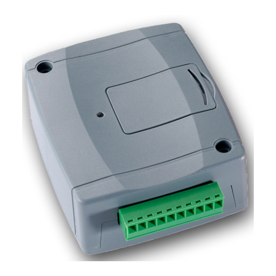
GSM 900MHz / 1800MHz Dimensions: 84 x 72 x 32mm Weight: 200g (packed: 300g) 9.2 Contents of the package • GPRS Pager 3 + terminal connector • GSM 900MHz / 1800MHz antenna • User manual, Letter of Guarantee, CD • USB A-B cable...
Need help?
Do you have a question about the GPRS Pager 3 and is the answer not in the manual?
Questions and answers