Table of Contents
Advertisement
Quick Links
HIGH SPEED, HIGH ACCURACY PERSONNEL
TESTER AND STAND
Installation, Operation and Maintenance
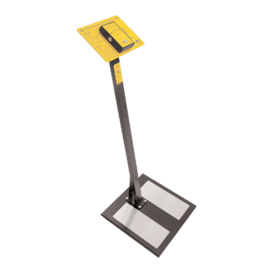
Figure 1. 222523 Personnel Test
Stand.
Description
A digital instrument with a
programmable IC at its heart that will
test the resistance of an operator's
grounding system(s) mounted on a
black metal frame with a black
wooden base board. The 222522 will
test the operator's ESD footwear.
The 222523 will additionally test the
operator's wrist strap. The stations
test both feet simultaneously. The
instrument will indicate whether the
resistance is in the ranges specified
in EN 61340-5 and ANSI/ESD S1.1 &
S20.20.
"Wrist straps shall be checked before
use. Each check shall be made with
the wrist band worn in contact with
the wearer's skin and with the ground
cord attached to the appropriate
tester." (EN 61340 5 1 paragraph 9.6
Daily checks, paragraph 9.6.2 Wrist
strap) "Where toe and heel straps
are used as ESID footwear, once
these are worn outside the EPA [ESD
protected area], particularly on
carpets, they are likely to accumulate
fluff and become ineffective; this
Phone: 0044 (0) 1462 672005, Fax: 0044 (0) 1462 670440 • e-mail: Service@Vermason.co.uk, Internet: Vermason.co.uk
TB-7536 December 2008 Page 1 of 2
TECHNICAL BULLETIN TB-7536
requires that they be checked or
replaced on every visit to the EPA.
...When ESD footwear is used, it
should be noted that ESD footwear
alone cannot achieve protection, but
needs to be used in conjunction with
a suitable ESID floor." (EN 61340-5-2
Paragraph 5.2.8 Footwear) "All
wearers shall check that their heel
and toe straps meet requirements [of
Table 1 NOTE 2 – 'When the
footwear/floor systems are used as
the primary means of grounding
personnel, the resistance of the
combination shall be determined by
the ESD co-ordinator, and is
recommended to be between 7,5 x
10E5 ohms1 and 3,5 x 10E7 ohms'].
The check shall be made before
entering the EPA." (EN 61340 5-1
Daily checks, paragraph 9.6.3 Non-
permanent footwear)
Inspection
Remove the test unit from the carton
and inspect for shipping damages.
Each 222522 unit should include the
following:
1 Test unit, item #222522
1 Test Stand Assembly
Each 222523 unit should include the
following:
1 Test unit, item #222523
1 Test Stand Assembly
Installation
1. Remove the components from the
packaging.
2. Lay out the baseboard and upright
bar using the packaging to protect
the paintwork.
3. Stand the baseboard on the rear
edge and offer the upright to
connect the 2 leads and align the
4 bolt holes.
4. With the leads connected, feed the
surplus cord back into the upright,
and then fit the four bolts from the
top. The washers and nuts can
then be fitted and tightened.
UNIT C, 4TH DIMENSION, FOURTH AVENUE, LETCHWORTH, HERTS, SG6 2TD UK
5. Stand the test stand up.
6. Insert the tester plugs through the
two larger holes in the instruction
panel. The connectors on the back
of the tester fit into the sockets on
the upright.
7. Place both in position, using the
two M5 bolts to secure the tester
& panel to the upright.
8. Perform a check on each plate
individually to check the
connections. If practical, remove a
shoe and stand in stockinged feet
on one footplate. Perform a test -
you should obtain a pass or fail
low. (Most likely fail low). Repeat
the test with the foot on the other
test plate.
9. The test station is now ready for
use.
Procedure to test footwear
1. Wear ESD shoes or heel
grounders as prescribed.
2. Stand on the footplates.
3. Press the round metal button on
the tester with one or two fingers.
The tester will now indicate
whether the total resistance is
within the acceptable range.
4. Green light and buzzer indicate
that the total resistance is either
less than 10MΩ or less than
35MΩ.
Green = OK
You may now enter the EPA.
5. A red light indicates non-
conformance.
Red = FAIL
Do not proceed in the usual
manner but contact your
supervisor or follow your company
procedure.
6. Contact your supervisor if the
battery low light comes on.
Procedure to test wrist strap
1. Wear wristband. Choose one that
fits snugly or adjust it to do so.
2. Connect the ground cord securely
to the band using the snap
connector.
3. Connect the other end of the cord
to a matching termination on the
tester.
© 2008 Vermason
Made in Britain
Advertisement
Table of Contents

Related Manuals for Vermason 222523

Summary of Contents for Vermason 222523
- Page 1 UNIT C, 4TH DIMENSION, FOURTH AVENUE, LETCHWORTH, HERTS, SG6 2TD UK Phone: 0044 (0) 1462 672005, Fax: 0044 (0) 1462 670440 • e-mail: Service@Vermason.co.uk, Internet: Vermason.co.uk TB-7536 December 2008 Page 1 of 2 © 2008 Vermason...
- Page 2 They are current 12µA max measured using an ohmmeter, which UNIT C, 4TH DIMENSION, FOURTH AVENUE, LETCHWORTH, HERTS, SG6 2TD UK Phone: 0044 (0) 1462 672005, Fax: 0044 (0) 1462 670440 • e-mail: Service@Vermason.co.uk, Internet: Vermason.co.uk TB-7536 Page 2 of 2...
Need help?
Do you have a question about the 222523 and is the answer not in the manual?
Questions and answers