Table of Contents
Advertisement
Quick Links
Advertisement
Table of Contents

Related Manuals for Metra Electronics ELS NET LC16ANT


Summary of Contents for Metra Electronics ELS NET LC16ANT
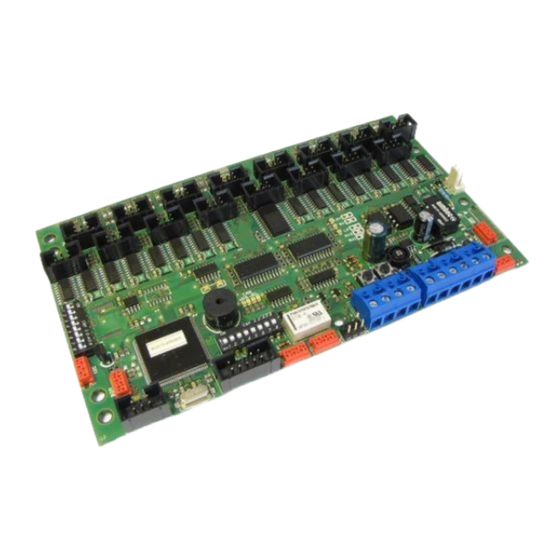
- Page 1 Locker Controller ELS NET Technical Manual...
-
Page 2: Table Of Contents
Locker Controller ELS NET Technical Manual Table of contents Locker Controller ELS NET Technical Manual ..................4 Product description ..........................4 Basic Parts ............................5 Locker Controller PCB with two extension modules and connecting PCB ........5 Emergency Open Push-button (optional) ..................5 ELS NET Tester (optional) ....................... - Page 3 Locker Controller ELS NET Technical Manual Device replacement .......................... 22 Maintenance ............................. 22 Troubleshooting Guide ........................23 Technical data ........................... 23 Appendix ............................23 Page 3...
-
Page 4: Locker Controller Els Net Technical Manual
Locker Controller ELS NET Technical Manual Locker Controller ELS NET Technical Manual Manufacturer: Metra inženiring d.o.o. phone: +386 1 56 10 740 IOC Trzin fax: +386 1 56 10 744 Špruha 19 web: www.metra.si SI-1236 Trzin, Slovenia System: Metra ELS NET – Electronic Locking Systems Product Group: Locker Controller ... -
Page 5: Basic Parts
Locker Controller ELS NET Technical Manual Locker Controller also supports emergency and security features. A pushbutton for emergency opening of all Lockers connected to the Locker Controller (and belonging extension modules) is fitted on the main electronics board and also an external emergency pushbutton can be connected. In case of attempt of break-in an Alarm message is distributed over Metra NET Network to Metra user interface devices and over Metra Network Controller to LAN / WAN and Metra software. -
Page 6: Connections
Locker Controller ELS NET Technical Manual Connections description description Electronic Lock 1 Electronic Lock 27 Electronic Lock 2 Electronic Lock 28 Electronic Lock 3 Electronic Lock 29 Electronic Lock 4 Electronic Lock 30 Electronic Lock 5 Electronic Lock 31 Electronic Lock 6 Electronic Lock 32 Electronic Lock 7... -
Page 7: Connecting Locker Extension Modules
Locker Controller ELS NET Technical Manual *NOTE: Local CAN connectors are internally parallel connected. **NOTE: Local CAN connectors are internally parallel connected. ***NOTE: Local CAN connectors are internally parallel connected. ****NOTE: 12V DC Power connectors are internally parallel connected. Connecting Locker Extension Modules When Locker Controller without mounting plate is used connect up to two Extension modules by 6 wire flat cable. -
Page 8: Connecting Electronic Locks
Locker Controller ELS NET Technical Manual Connecting Electronic Locks Connect Electronic Locks using 6 wire flat cable. Maximum length of each cable is 20 meters. Cables from Electronic Locks with lower locker numbers must be connected to lower index connector. -
Page 9: Power Supply Connection (Locker Controller With Distribution Board)
Locker Controller ELS NET Technical Manual Power supply connection (Locker Controller with distribution board) Regulated 12 VDC power supply is required for proper operation. Connect as many units as possible to a single power supply unit. Consult the Technical Specifications section of this document for current consumption. -
Page 10: Metra Net Network Connection (Locker Controller Without Distribution Board)
Locker Controller ELS NET Technical Manual Metra NET Network connection (Locker Controller without distribution board) The Metra NET Network connection provides for operational functionality of the Locker Controller. Different devices in parallel can be connected to the Metra Network Controller by a single unshielded twisted pair (UTP) cable. -
Page 11: External Emergency Open Pushbutton Connection (Optional)
Locker Controller ELS NET Technical Manual External emergency open pushbutton connection (optional) Connect the blue and blue/white wires of the UTP cable from the Emergency open pushbutton to designated terminals as shown in the schematic. Page 11... -
Page 12: Els Net Tester Connection (Optional)
Locker Controller ELS NET Technical Manual ELS NET Tester connection (optional) Connect the 6 pole flat cable to the connector marked “I2C” connector as shown in the schematic. DIP switch settings description description Emergency open pushbutton Network Address DIP switch Parameters request button Operating Mode DIP Switch Page 12... -
Page 13: Network Address
Locker Controller ELS NET Technical Manual By changing the Operating Mode DIP Switch pins positions, different operating modes and parameters can be set and by changing the Network Address DIP Switch pins positions, different network address can be set. To change between different pins positions, use a small flat headed screwdriver or similar object to push DIP switch pins to desired position. -
Page 14: Operating Modes
Locker Controller ELS NET Technical Manual Operating modes NORMAL mode of operation TEST mode of operation Page 14... -
Page 15: Signalization
Locker Controller ELS NET Technical Manual Signalization Power-on When power is applied the following LEDs are on: Yellow LED on Locker Controller (12VDC present) Green LED on Locker Controller (5VDC regulated on board active) Yellow LED on Extension Module(s) (12VDC present) ... -
Page 16: Network Communication
Locker Controller ELS NET Technical Manual Each Locker Controller and Locker Extension Module has a blinking green LED operating indicator. All these signals are under software control indicating that the device is running. Network Communication Network communication (Metra NET) is signalled on the Locker Controller by four LEDs: ... -
Page 17: Emergency Open Procedure
Locker Controller ELS NET Technical Manual Check if correct operating parameters were downloaded. See chapter “Functional Test” for more details Emergency Open procedure Locker Controller features an Emergency Open procedure, which unlocks all Electronic Locks connected to the Locker Controller and to all of the attached Locker Extension Modules. Locks are unlocked one by one, starting at the lock connected to the leftmost connector (position #1). -
Page 18: Test Mode Activation
Locker Controller ELS NET Technical Manual Test mode activation STEP 1: With small flat headed screwdriver or similar tool set switches 1 to 4 located on the “Operating mode DIP switch” to ON (switch up). STEP 2: Connect the ELS NET Tester to the Locker Controller as described in the paragraph “ELS NET Tester connection”. -
Page 19: Testing Electronic Locks Installation
Locker Controller ELS NET Technical Manual Testing electronic locks installation STEP 1: Close the locker door. STEP 2: Locker index (1-32 as it is connected to the Locker Controller) is displayed. STEP 3: Locking time in milliseconds is displayed shortly after locker index. -
Page 20: Testing Parameter Request Button
Locker Controller ELS NET Technical Manual STEP 5: Electronic Lock unlocks and the locker opens. STEP 6: Unlocking time in milliseconds is displayed shortly after locker index. Unlocking time should be between 150 and 300. NOTE You can repeat this procedure on all lockers connected to Locker Controller board. -
Page 21: Testing Emergency Open Pushbutton
Locker Controller ELS NET Technical Manual “0000” is displayed shortly after. To cancel parameters request pushbutton test press leftmost pushbutton bellow the 4 digit LED display on the ELS NET Tester. Testing Emergency open pushbutton Internal: Press the Emergency open pushbutton. External: Turn the key on emergency open pushbutton clockwise to initiate emergency opening of all Lockers. - Page 22 Locker Controller ELS NET Technical Manual Signalization: “EOPn” is displayed and all lockers connected to the Locker Controller start to unlock and open one after another and corresponding locker numbers are displayed. NOTE: To stop the emergency unlocking procedure press the Emergency open pushbutton again.
- Page 23 Locker Controller ELS NET Technical Manual Troubleshooting Guide trouble explanation / solution Locker door closed while locking and nothing happens. Adjust the door strike. Check the Electric Lock. Replace the Electric Lock if necessary. The Locker door not ejected when unlocked. Adjust the door strike.
- Page 24 Locker Controller ELS NET Appendix 1 Physical dimensions Locker Controller 75.5 6 7 8 Locker Controller Extension Module 1 2 3 4...
- Page 25 Locker Controller ELS NET Appendix 2 Physical dimensions Mounting rails 6 7 8...
- Page 26 Locker Controller ELS NET Appendix 3 Physical dimensions Mounting plate 46.5 46.5...
- Page 27 Locker Controller ELS NET Appendix 4 Network schematic Metra NET Network up to 1 km / up to 60 devices Line Terminator Locker Controller 1 Locker Controller 2 Locker Controller N Reader Reader Terminal 1 Terminal N Electric Locks Electric Locks Electric Locks BANK OF LOCKERS 1 BANK OF LOCKERS 2...
- Page 28 Locker Controller ELS NET Appendix 5 Device configuration example Reader Terminal 6 7 8 1 2 3 4 1 2 3 4 OPTIONAL To other Metra devices...
Need help?
Do you have a question about the ELS NET LC16ANT and is the answer not in the manual?
Questions and answers