
Summary of Contents for Pololu Zumo Shield For Arduino
- Page 1 Pololu Zumo Shield for Arduino User’s Guide © 2001–2019 Pololu Corporation Pololu Zumo Shield for Arduino User’s Guide https://www.pololu.com/docs/0J57/all Page 1 of 52...
-
Page 2: Table Of Contents
1.a. Contacting Pololu ........ -
Page 3: Overview
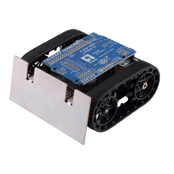
Pololu Zumo Shield for Arduino User’s Guide © 2001–2019 Pololu Corporation 1. Overview The Zumo Shield provides a convenient interface between our Zumo chassis [https://www.pololu.com/ and an A-Star 32U4 Prime Arduino product/1418] [https://www.pololu.com/category/165/a-star-32u4-prime] , or Arduino Leonardo (it is [https://www.pololu.com/product/2191] [https://www.pololu.com/product/2192]... -
Page 4: Contacting Pololu
Pololu Zumo Shield for Arduino User’s Guide © 2001–2019 Pololu Corporation The latest revision of the Zumo Shield is version 1.2. This version adds an L3GD20H 3-axis gyroscope upgrades accelerometer [https://www.pololu.com/product/2129] magnetometer chip to the newer LSM303D . It is available by itself, [https://www.pololu.com/product/2127]... -
Page 5: Included Components
Pololu Zumo Shield for Arduino User’s Guide © 2001–2019 Pololu Corporation 1.b. Included components The Zumo Shield is available: • by itself [https://www.pololu.com/product/2508] • as part of a Zumo robot kit for Arduino that also includes [https://www.pololu.com/product/2509] Zumo chassis and a stainless steel Zumo blade [https://www.pololu.com/product/1418]... - Page 6 Pololu Zumo Shield for Arduino User’s Guide © 2001–2019 Pololu Corporation Zumo Robot Kit for Arduino In addition to the shield and its included hardware, the Zumo robot kit for Arduino also includes these components: • Zumo chassis [https://www.pololu.com/product/1418] which includes: ◦...
- Page 7 Pololu Zumo Shield for Arduino User’s Guide © 2001–2019 Pololu Corporation Zumo Robot for Arduino The Zumo robot for Arduino is a fully-assembled robot platform built from the same components found in the Zumo robot kit for Arduino, along with these additions: •...
-
Page 8: Assembly
Pololu Zumo Shield for Arduino User’s Guide © 2001–2019 Pololu Corporation 2. Assembly If you have a Zumo robot kit for Arduino or a separate Zumo [https://www.pololu.com/product/2509] Shield chassis , this section [https://www.pololu.com/product/2508] [https://www.pololu.com/product/1418] will guide you through assembling them into a complete robot. -
Page 9: Assembling The Zumo Shield And Chassis
Pololu Zumo Shield for Arduino User’s Guide © 2001–2019 Pololu Corporation [https://www.pololu.com/category/123/pololu-qtr-reflectance-sensors] • Connectors and jumper wires , for connecting [https://www.pololu.com/category/19/connectors] additional sensors and components • Battery charger (such as the iMAX-B6AC ), if you are using [https://www.pololu.com/product/2588] rechargeable batteries Assembly tools •... - Page 10 Pololu Zumo Shield for Arduino User’s Guide © 2001–2019 Pololu Corporation Through-hole parts 1. Solder the included through-hole components to the shield: ◦ power switch ◦ reset pushbutton ◦ user pushbutton ◦ buzzer ◦ charging connector (1×2-pin female header) 2. On the bottom of the board, trim any leads longer than 1/16″ (the thickness of the spacer plate) so they do not prevent the shield from sitting flat on the spacer plate and chassis.
- Page 11 Pololu Zumo Shield for Arduino User’s Guide © 2001–2019 Pololu Corporation one 1×10 header, two 1×8 headers, and one 1×6 header; older Arduino boards use two 1×8 headers and two 1×6 headers (the two pairs of pins highlighted above in red should not be populated if you are using this board with an older Arduino that does not support these additional pins).
- Page 12 Pololu Zumo Shield for Arduino User’s Guide © 2001–2019 Pololu Corporation Jumpers and additional connections 5. Optional: If you want to enable the buzzer, enable the battery level input, or disable the compass, now is a good time to add and/or cut jumper connections to configure the shield to your liking.
- Page 13 Pololu Zumo Shield for Arduino User’s Guide © 2001–2019 Pololu Corporation 6. Optional: At this point, you might consider soldering additional components (such as sensors), or headers or wires for connecting them, to the shield. If you do this, please check to make sure your part placement does not interfere with the shield’s ability to mate with the...
- Page 14 Pololu Zumo Shield for Arduino User’s Guide © 2001–2019 Pololu Corporation 8. Cut two of the included jumper wires in half to form four segments, and trim off the ends that are covered in adhesive (the adhesive could interfere with making a good electrical connection to the motor).
- Page 15 Pololu Zumo Shield for Arduino User’s Guide © 2001–2019 Pololu Corporation Each motor’s positive terminal is indicated by a plus sign (+) in the black plastic end of the motor, as indicated in the picture below. The motors should be soldered into the shield with the positive terminal closest to the front, so you should attach the leads to allow the motors to be oriented this way.
- Page 16 Pololu Zumo Shield for Arduino User’s Guide © 2001–2019 Pololu Corporation Chassis and shield To assemble the chassis with the Zumo Shield, you should use the two-piece acrylic spacer plate that is included with the shield. You will not need the one-piece mounting plate that is included with the Zumo chassis.
- Page 17 Pololu Zumo Shield for Arduino User’s Guide © 2001–2019 Pololu Corporation holes in the spacer plate should line up with the through-holes in the shield resting on top of it, and the motor leads should be aligned so they pass through the slots in the spacer as shown in the picture below.
- Page 18 Pololu Zumo Shield for Arduino User’s Guide © 2001–2019 Pololu Corporation mounting a sumo blade; otherwise, you can use the shorter 1/4″ screws for all four mounting holes. If you are also adding a basic sumo blade, you can either mount it now or add it later after you are done soldering the motors and battery contacts.
- Page 19 Pololu Zumo Shield for Arduino User’s Guide © 2001–2019 Pololu Corporation the shield so that the holes line up with the two front mounting holes and insert the two longer (5/16″) #2-56 machine screws (included with the shield) through the blade, shield, spacer plate, and chassis.
- Page 20 Pololu Zumo Shield for Arduino User’s Guide © 2001–2019 Pololu Corporation Battery contacts 16. Turn the chassis over and install the battery terminal contacts as shown in the picture below. The three double-contact pieces should be firmly pressed into place until they are flush with the interior surface of the battery compartment.
- Page 21 Pololu Zumo Shield for Arduino User’s Guide © 2001–2019 Pololu Corporation 17. Solder the two individual contacts to the shield from the top. Note that if you are using a battery to hold the contact in place during soldering, the battery might act as a heat sink, making it more difficult to solder or requiring a higher soldering iron temperature.
- Page 22 Pololu Zumo Shield for Arduino User’s Guide © 2001–2019 Pololu Corporation 20. At this point, you can add the silicone tracks by stretching them around the sprockets on each side of the chassis. Your Zumo Shield and chassis are now complete; just add batteries and an Arduino to get your Zumo robot moving! 2.
-
Page 23: Adding A Zumo Reflectance Sensor Array (Optional)
Pololu Zumo Shield for Arduino User’s Guide © 2001–2019 Pololu Corporation Disassembly If you later decide you want to solder additional parts to the Zumo Shield, it is possible to remove it from the chassis with some careful effort. 1. Remove the tracks from the chassis. - Page 24 Pololu Zumo Shield for Arduino User’s Guide © 2001–2019 Pololu Corporation Assembling the sensor array The Zumo reflectance sensor array ships with all of the components you need to connect it to a Zumo shield: • sensor array PCB with the surface- mount parts pre-populated •...
- Page 25 Pololu Zumo Shield for Arduino User’s Guide © 2001–2019 Pololu Corporation We recommend using the right-angle header mounted as shown in the picture below, but the straight 3-pin header will also work if you do not have anything already soldered to the Zumo shield’s front expansion area that would interfere.
- Page 26 Pololu Zumo Shield for Arduino User’s Guide © 2001–2019 Pololu Corporation With the female header in place, the assembled sensor array can be plugged directly into the Zumo shield. 2. Assembly Page 26 of 52...
- Page 27 Pololu Zumo Shield for Arduino User’s Guide © 2001–2019 Pololu Corporation The reflectance sensor array features two visible (red) LEDs in series with the IR emitter LEDs, so you can use the red LEDs to tell when the emitters are on and off.
- Page 28 Pololu Zumo Shield for Arduino User’s Guide © 2001–2019 Pololu Corporation Disabling or remapping sensors Many applications do not require all six reflectance sensors, and you might want additional I/O lines for other things (e.g. obstacle detectors). In such cases, you can disable specific sensors and free up their associated I/O lines.
- Page 29 Pololu Zumo Shield for Arduino User’s Guide © 2001–2019 Pololu Corporation Now you effectively have a four-sensor array and analog pins A2 and A3 are available for general- purpose use. To configure the object to use this new configuration, call...
-
Page 30: The Zumo Shield In Detail
Pololu Zumo Shield for Arduino User’s Guide © 2001–2019 Pololu Corporation 3. The Zumo Shield in detail 3.a. Features and components The main features of the Zumo Shield (v1.2) are labeled in this diagram: For the original Zumo Shield, a corresponding diagram [https://www.pololu.com/file/0J810/zumo-shield-... - Page 31 Pololu Zumo Shield for Arduino User’s Guide © 2001–2019 Pololu Corporation edge of the shield, which can be used to recharge the Zumo’s batteries without removing them from the chassis. The positive pin of the charge connector, on the left, is indicated by a plus sign (+). A...
- Page 32 Pololu Zumo Shield for Arduino User’s Guide © 2001–2019 Pololu Corporation the Arduino’s internal pull-up to pull the pin high otherwise. The Pushbutton part of our Zumo Shield Arduino library , makes it easy to detect and [https://www.pololu.com/docs/0J57/6] debounce button presses with this pushbutton.
-
Page 33: Front Expansion
Pololu Zumo Shield for Arduino User’s Guide © 2001–2019 Pololu Corporation • The v1.2 Zumo Shield features an LSM303D 3-axis accelerometer and magnetometer and an L3GD20H 3-axis gyroscope. • The original Zumo Shield features an LSM303DLHC 3-axis accelerometer and magnetometer. -
Page 34: Jumper Settings
Pololu Zumo Shield for Arduino User’s Guide © 2001–2019 Pololu Corporation pins on the Zumo Shield will not be connected to anything. To use an I²C device on those pins, you can connect SDA to A4 and SCL to A5 yourself by bridging across those two sets of pins in the front expansion area. - Page 35 Pololu Zumo Shield for Arduino User’s Guide © 2001–2019 Pololu Corporation • The battery level jumper connects the Arduino’s analog pin 1 to a voltage divider circuit that allows you to monitor the Zumo’s battery voltage. This jumper is disconnected by default and can be connected by soldering a short length of wire between the two holes.
-
Page 36: Inertial Sensors (Accelerometer, Magnetometer, And Gyro)
Pololu Zumo Shield for Arduino User’s Guide © 2001–2019 Pololu Corporation with the label 32U4 to connect the BZ pin to digital pin 6. These are the pins our Zumo Shield Arduino library expects the buzzer to be connected to for each respective [https://www.pololu.com/docs/0J57/6]... - Page 37 Pololu Zumo Shield for Arduino User’s Guide © 2001–2019 Pololu Corporation All versions of the Zumo Shield have a compass module that combines a 3-axis accelerometer and 3-axis magnetometer into a single package with an I²C interface. This chip is an LSM303D on the v1.2 shield or an...
- Page 38 Pololu Zumo Shield for Arduino User’s Guide © 2001–2019 Pololu Corporation a particular environment, they can be used to help the Zumo turn left or right by a specific angle instead of just timing how long to run the motors to make such a turn.
-
Page 39: Schematic Diagrams
Pololu Zumo Shield for Arduino User’s Guide © 2001–2019 Pololu Corporation 4. Schematic diagrams Schematic diagrams of the Zumo Shield are available as a downloadable PDF: • v1.2 Zumo Shield schematic diagrams [https://www.pololu.com/file/0J779/zumo-shield- (449k pdf) v1_2-schematic.pdf] • Original Zumo Shield... -
Page 40: Arduino Pin Assignment Table
Pololu Zumo Shield for Arduino User’s Guide © 2001–2019 Pololu Corporation 5. Arduino pin assignment table Digital Zumo Shield function Notes/alternate functions pins RX for programming and serial communication on Uno and older digital I/O Arduinos TX for programming and serial communication on Uno and older... -
Page 41: Zumo Shield Arduino Library
Pololu Zumo Shield for Arduino User’s Guide © 2001–2019 Pololu Corporation 6. Zumo Shield Arduino library Our Zumo Shield Arduino library makes it easy to get started writing Arduino sketches to control your Zumo. A link to download the library and installation instructions can be found on the library’s... - Page 42 Pololu Zumo Shield for Arduino User’s Guide © 2001–2019 Pololu Corporation to generate pulse width modulation at a 20 kHz frequency. (See Section 3 for more details about the motor driver and its connections.) If you accidentally soldered a motor to the Zumo Shield backwards (opposite the orientation indicated...
- Page 43 Pololu Zumo Shield for Arduino User’s Guide © 2001–2019 Pololu Corporation sensors . Since the Zumo reflectance [https://www.pololu.com/category/123/pololu-qtr-reflectance-sensors] sensor array has the same interface as the QTR RC reflectance [https://www.pololu.com/product/1419] sensors, the ZumoReflectanceSensorArray library uses QTRSensors to read the sensor array.
-
Page 44: Example Sketches
Pololu Zumo Shield for Arduino User’s Guide © 2001–2019 Pololu Corporation 7. Example sketches These examples demonstrate how to program an Arduino-controlled Zumo to perform more complex and interesting tasks. The source files for the examples are included in the download for the... -
Page 45: Simple Border-Detecting Sumo Robot
Pololu Zumo Shield for Arduino User’s Guide © 2001–2019 Pololu Corporation Diagram of an RC receiver connected to pins on a Zumo Shield. This program uses Arduino’s PulseIn library to read the signals [http://arduino.cc/en/Reference/PulseIn] from the receiver. By default, it assumes the throttle and steering channels are connected as the diagram shows on pins 4 and 5, respectively. - Page 46 Pololu Zumo Shield for Arduino User’s Guide © 2001–2019 Pololu Corporation A Zumo robot preparing to attack a Parallax SumoBot. Zumo reflectance sensor array on a Zumo robot, bottom view. This example demonstrates how to program an Arduino-controlled Zumo equipped with a reflectance sensor array to drive around and stay within a sumo ring.
-
Page 47: Collision-Detecting Sumo Robot
Pololu Zumo Shield for Arduino User’s Guide © 2001–2019 Pololu Corporation • If you do not hear any sound from the buzzer, make sure you have the buzzer control jumper configured correctly for your Arduino. [https://www.pololu.com/docs/0J57/3.c] The ability to wander around while staying inside a sumo ring is enough to allow a Zumo to compete as a basic sumo robot, but a more advanced robot might be able to detect its opponent and drive toward it directly. -
Page 48: Using The Compass
Pololu Zumo Shield for Arduino User’s Guide © 2001–2019 Pololu Corporation , and the concepts and strategies involved are explained in detail in [https://www.pololu.com/product/975] Section 8 of the 3pi robot user’s guide [https://www.pololu.com/docs/0J21] 7.f. Using the compass This example program demonstrates using the magnetometer in the Zumo Shield’s LSM303 3-axis... -
Page 49: Controlling A Servo
Pololu Zumo Shield for Arduino User’s Guide © 2001–2019 Pololu Corporation 8. Controlling a servo This section explains how to control a hobby RC servo from [https://www.pololu.com/category/23/rc-servos] an Arduino Uno, Arduino Leonardo, or A-Star 32U4 Prime that is connected to the Zumo Shield. - Page 50 Pololu Zumo Shield for Arduino User’s Guide © 2001–2019 Pololu Corporation /** Arduino Uno Timer 2 Servo Example This example code for the Arduino Uno shows how to use Timer 2 on the ATmega328P to control a single servo. This can be useful for people who cannot use the Arduino IDE's Servo library.
-
Page 51: Controlling A Servo With An Arduino Leonardo Or A-Star 32U4 Prime
Pololu Zumo Shield for Arduino User’s Guide © 2001–2019 Pololu Corporation // The servo pin is currently high. // Check to see if is time for a falling edge. // Note: We could == instead of >=. if(servoTime >= highTimeCopy) // The pin has been high enough, so do a falling edge. - Page 52 Pololu Zumo Shield for Arduino User’s Guide © 2001–2019 Pololu Corporation with ZumoMotors, making it possible to simultaneously control servos and the motors. Warning: The modifications described here will affect any sketch for the Arduino Leonardo or A-Star that uses the Servo library.
Need help?
Do you have a question about the Zumo Shield For Arduino and is the answer not in the manual?
Questions and answers