
Subscribe to Our Youtube Channel
Related Manuals for Nanoptix ULTRA SYSTEM

Summary of Contents for Nanoptix ULTRA SYSTEM
- Page 1 Owner’s Manual First Edition – April 18, 2017 Last Revised – April 23, 2020 Document # 700075-0000R...
- Page 2 Legal Notices Disclaimer Information in this document is subject to change without notice. Consult your Nanoptix Inc. sales representative for information that is applicable and current. Nanoptix Inc. reserves the right to improve products as new technology, components, software, and firmware become available.
- Page 3 AC line filtering, over-current and short-circuit protection. The use of these products with a power supply other than a Nanoptix Inc. approved one will require you to test the power supply with the Nanoptix Inc. product for FCC and CE mark certification.
-
Page 4: Table Of Contents
About the Wireless Ultra System ................... 1 Game Interface General specifications ................... 1 Spill Proof Printer General Specifications ................2 1 Description of the Wireless Ultra System ..............3 Game Interface configured as “HOST” ..............4 Game Interface configured as “GAME” ..............4 Digi Xbee Wireless Module .................. - Page 5 WIRELESS ULTRA SYSTEM OWNER’s Manual Figures 1: W ............3 IGURE IRELESS LTRA YSTEM 2: G – “HOST” ............. 4 IGURE NTERFACE 3: G – “GAME” ............. 4 IGURE NTERFACE 4: S ............... 5 IGURE PILL ROOF RINTER 5: C ................
-
Page 6: About The Wireless Ultra System
WIRELESS ULTRA SYSTEM OWNER’s Manual About the Wireless Ultra System Game Interface General specifications Operating Temperature ° ° C to +85 Operating Relative Humidity 5% to 90% RH at 50C (non-condensing) Communication 2.4GHz OQPSK with DSSS Range 200 ft (60m), PRO 300 ft (90m) -
Page 7: Spill Proof Printer General Specifications
WIRELESS ULTRA SYSTEM OWNER’s Manual Spill Proof Printer General Specifications Print Method Direct Thermal 8 dot/mm (203 dpi) Resolution Print Width 80mm Paper Width 80mm or 82.5 mm Max Roll Diameter 82.5mm Operating Temperature 0 to 50 C Storage Temperature... -
Page 8: Description Of The Wireless Ultra System
OWNER’s Manual 1 Description of the Wireless Ultra System The Wireless Ultra System has been designed to manage small game rooms. With simple non- intrusive connections, the system can be scaled up or down to adapted to different needs. From remotely clearing credits and printing behind the counter, to acting as a complete bookkeeping center. -
Page 9: Game Interface Configured As "Host
WIRELESS ULTRA SYSTEM OWNER’s Manual 1.1 Game Interface configured as “HOST” The HOST is the central controller of the system and functions as a hub between all components. The HOST is connected to the control box via an RJ-12 connector. The printer communicates with and provides power to the HOST via a 10 pin Molex connector. -
Page 10: Digi Xbee Wireless Module
1.4 Spill Proof Printer The Nanoptix Spill-Proof thermal printer is extremely fast, quiet, and very reliable. With thermal printing technology, there is no ribbon cassette to change, and paper loading is extremely simple. -
Page 11: Control Box
WIRELESS ULTRA SYSTEM OWNER’s Manual 1.5 Control Box The Control Box is the user interface of the Wireless Ultra System. It is used to remotely clear credits and print bookkeeping information. Figure 5: Control Box 1.5.1 Control Box Operation ... -
Page 12: Meters
The key meter report will be printed immediately and will ALWAYS be cleared following the report. The Central Meter “Remote Access” This meter can be accessed remotely. The accumulated data is accessed by a customized application such as Nanoptix WINDSHIELD software. Document # 700005-0000R April 3, 2019... -
Page 13: Configuration And Setup
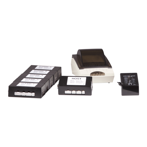
WIRELESS ULTRA SYSTEM OWNER’s Manual 3 Configuration and Setup Figure 6: Wireless Ultra System 1. Power off all gaming terminals 2. Remove Game Interface black boxes (C) from packaging and place inside each gaming terminal that you wish to monitor with the system. - Page 14 WIRELESS ULTRA SYSTEM OWNER’s Manual 5. Cable (B) part # 210029-0121R “BLUE-RED-BLACK” Attach the blue wire (FORCE CASHOUT) to the gaming terminal’s “knock-off” button using the enclosed red wiretaps Attach the red wire (+12Vdc - SUPPLY VOLTAGE) to the +12 VDC of the gaming terminal’s power supply using the enclosed red wiretaps.
-
Page 15: Dip Switch Settings
WIRELESS ULTRA SYSTEM OWNER’s Manual 4 DIP Switch Settings HOST BOX DIP Switch # 1 Function Cashless System 1 (default) Accounting Only System Figure 7: DIP Switches DIP Switch # 2 Function GAMES BOXES (1 to 5) 0 (default) Nanoptix Scanner/LCD... -
Page 16: Communication Ports
WIRELESS ULTRA SYSTEM OWNER’s Manual 5 Communication Ports 5.1 Spill Proof Serial RS-232 Port - 9 pin DB9 Signal Name Spill Proof I/O Game Interface I/O Function Aux power Output Input Power HOST (5VDC) PRT_TXD Output Input Transmit PRT_RXD Input... -
Page 17: Ordering Miscellaneous Supplies
WIRELESS ULTRA SYSTEM OWNER’s Manual 6 Ordering Miscellaneous Supplies Power Supply and Power Cord Part Part Number Power Supply (24VDC, 2.5A max, 60W) 270034-0002R Power cord (North America) 102080-0000R Power Cord (Continental Europe) 102080-0001R Table 7: Power Supply part numbers... -
Page 18: Troubleshooting
Table 10: Game Interface LED status 7.2.2 Power on information ticket Every time the Wireless Ultra System is turned on, a power-on ticket will be printed by the Spill Proof printer. The resident status ticket lists the firmware version current settings. This ticket can also be used as confirmation that the HOST game interface is communicating with the Spill Proof printer. -
Page 19: Testing The Spill Proof Printer
WIRELESS ULTRA SYSTEM OWNER’s Manual 7.3 Testing the Spill Proof Printer 7.3.1 LED Status Condition LED Status Unit ready Unit is in Reset or Booting Paper Out Slow Blink Temperature, Voltage, Print head error Med Blink Cover open, Paper jam... -
Page 20: Maintenance & Cleaning Instructions
The CENTRAL meters information can be retrieved by connecting the HOST game interface to the internet. This information can be customized and displayed by website or software program such as Nanoptix WINDSHIELD For additional information, contact Nanoptix Support.
Need help?
Do you have a question about the ULTRA SYSTEM and is the answer not in the manual?
Questions and answers