Gecko in.xe Tech Book
Swim spa system
Hide thumbs
Also See for in.xe:
- Tech book (56 pages) ,
- Quick start card (2 pages) ,
- Startup manual (14 pages)
Table of Contents
Advertisement
Advertisement
Table of Contents

Related Manuals for Gecko in.xe


Summary of Contents for Gecko in.xe
- Page 1 TechBook Swim spa systems When two are better than one! Versatility Power Control...
-
Page 3: Table Of Contents
Table of contents Warnings ������������������������������������������������������������������������������������������������������������������������������������������������������������������������� 2 Introduction ��������������������������������������������������������������������������������������������������������������������������������������������������������������������� 3 Overview - in�xe overview ����������������������������������������������������������������������������������������������������������������������������������������������������� 4 - 5 pump swim spa configuration overview ����������������������������������������������������������������������������������������������������������� 4 Installation - in�xe control systems installation procedure ������������������������������������������������������������������������������������������������������� 5 - Swim spa control systems installation diagram ��������������������������������������������������������������������������������������������������� 5 - Keypad installation ���������������������������������������������������������������������������������������������������������������������������������������������... -
Page 4: Warnings
STRUCTURE ARE NOT SPECIFIED AS LONG AS THEY ARE SUFFICIENT SO THAT THE AMBIENT TEMPERATURE AROUND THE CONTROLLER DOES NOT EXCEED 50 OR 60°C� Aeware , Gecko , and their respective logos are Registered Trademarks of Gecko Alliance Group� ® ® in�xe™, in�access™, in�keys™, in�touch™, in�k200™, in�k400™, in�k450™, in�k600™, K-19™, K-35™, K-8™, in�k1000™, in�k800™, in�k500™, in�k300™, in�flo™, in�put™, in�seal™, in�link™, in�t�cip™, in�stik™, heat�wav™, Y Series™... -
Page 5: Introduction
Introduction Swim spa systems When two are better than one! Gecko offers control systems for swim spas that truly take into account the unique relaxation and swimming features of this type of spas� Designed to be versatile and to provide a maximum of possible configurations, the Gecko system for swim spas includes two in�xe controllers, a main keyboard, an... -
Page 6: Overview
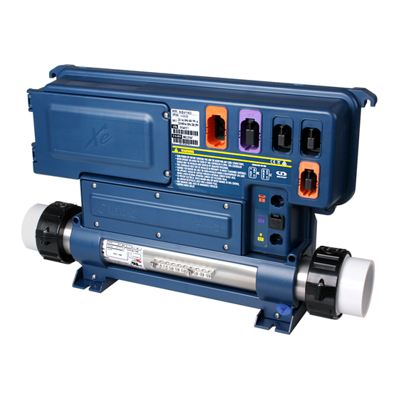
Mounting feet Bonding lug heat�wav Light output heater Note: No connectors should remain unplugged. Use blank plugs to fill unused connectors. * Available only on IN.XE-5. 5 pump swim spa configuration overview Pump 1 Pump 2 Ozonator Pump 3 Pump 4 Pump 5 in.split cable... -
Page 7: Installation
Installation in.xe control systems installation procedure For ground or wall installation of your in�xe control systems please refer to in�xe techbook, section installation for complete instructions Warning Leave a 2' distance between the MASTER in�xe and the SLAVE in�xe during installation (see diagram below)�... -
Page 8: Connections
Connections Connection of main and auxiliary keyads Note: Always shut power down before connecting an accessory to the in.xe. To connect the keypad insert the in�link connector into the appropriate keypad connector (as illustrated�) MASTER IN�XE Keypad SLAVE IN�XE Keypad... -
Page 9: Connecting High Voltage Accessories
Female connector on spa pack Connector 4 Connector 5 Connector C Connector CO Connector L1 in.link output connectors High-Current - HC connectors High-Current - HC connectors Master in.xe Slave in.xe Connector Output Typical Device Connector Output Typical Device Connector 1... -
Page 10: Wiring
Wiring in.link connector For more information on the in�xe in�link connectors, consult the “in�link”connector in the in�xe techbook�... -
Page 11: Electrical Wiring
Electrical wiring Electrical wiring: all models Warning Cut electrical power before proceeding to any electrical job� The wiring must be done by a qualified Main power electrician in accordance to Bonding lug local electric code� To complete the electrical connections of the control system you will need a Phillips screwdriver and a flat-head screwdriver�... -
Page 12: Electrical Wiring: North American Models - 1 Breaker
Electrical wiring Electrical wiring: North American models - 1 breaker Insert every wire in the appropriate control system terminal, in accordance to the color code indicated on the sticker� Use a Phillips screwdriver or a flat-head screwdriver to tighten the terminal screws� Connect the ground conductor wire to the front of the control system, (the ground conductors of the appartus should be connected with a grounded electrode)�... -
Page 13: Electrical Wiring: North American Models - 2 Breakers
Electrical wiring Electrical wiring: North American models - 2 breakers Insert every wire in the appropriate control system terminal, in accordance to the color code indicated on the sticker� Use a Phillips screwdriver or a flat-head screwdriver to tighten the terminal screws� Connect the ground conductor wire to the front of the control system, (the ground conductors of the appartus should be connected with a grounded electrode)�... -
Page 14: Electrical Wiring: European Models - Monophased
Electrical wiring Electrical wiring: European models - monophased Insert every wire in the appropriate control system terminal, in accordance to the color code indicated on the sticker� Use a Phillips screwdriver or a flat-head screwdriver to tighten the terminal screws� Connect the ground conductor wire to the front of the control system, (the ground conductors of the appartus should be connected with a grounded electrode)�... -
Page 15: Electrical Wiring: European Models - Biphased
Electrical wiring Electrical wiring: European models - biphased Insert every wire in the appropriate control system terminal, in accordance to the color code indicated on the sticker� Use a Phillips screwdriver or a flat-head screwdriver to tighten the terminal screws� Connect the ground conductor wire to the front of the control system, (the ground conductors of the appartus should be connected with a grounded electrode)�... -
Page 16: Electrical Wiring: European Models - Triphased
Electrical wiring Electrical wiring: European models - triphased Insert every wire in the appropriate control system terminal, in accordance to the color code indicated on the sticker� Use a Phillips screwdriver or a flat-head screwdriver to tighten the terminal screws� Connect the ground conductor wire to the front of the control system, (the ground conductors of the appartus should be connected with a grounded electrode)�... -
Page 17: Power Up And Breaker Setting
Power up and breaker setting IMPORTANT Please read the following before starting the device. Verify that all accessories are linked to the ground lug and connected to the control system. A minimum flow of 68 LPM (18 GPM) is required. Make sure that all valves are open in the spa plumbing and that the water flow is sufficient between the main pump and the water heater. - Page 18 Power up and breaker setting in.xe Selecting number of phases Menu not available 1 or 2 UL Swim 1 or 2 It is important to specify Choose the number of The values displayed by CE Swim 1, 2 or 3...
-
Page 19: Programming The Control System
Programming the control system Programming swim spa system with in.stik Communication port in.xe To download new preestablished internal configurations to the swim spa follow the following steps� Cut the power� When starting up, the If, at start up, the keypad Restart the system�... -
Page 20: Programming The Control System With The Keypad
Programming the control system Programming the control system with the keypad Although every in�xe The keypad will display Press on the Prog� key control system is factory L xx� “xx” corresponds to to confirm the chosen configured, in certain the number of the low-level configuration�... -
Page 21: Field Programming Options For Control Systems
Pump 3 low speed (simulates a direct) Pump 4 high speed Fountain (or P4 if only one speed) Auxiliary Pump 4 low speed Table 1 - in.xe Parameter Screen Options Description --,1H,1L,2H,2L,3H,3L,4H, 4L,P5,BL, Output 1 Accessory connected to the relay of output 1... - Page 22 CE/AUS/NZ or UL configuration CE/AUS/NZ = 1 Number of phases in.xe Number of phases/breaker Standard 1 (UL) Selection of number of phases (in.xe) 1 or 2 (CE) Menu not available Swim Spa 1 or 2 1 or 2 (UL) UL Swim...
- Page 23 Field programming options for control systems Table 2 - in.xe (older versions only) Parameter Screen Options Description --,1H,1L,2H,2L,3H,3L,4H, Output 1A Accessory connected to the relay of output 1A 4L,P5,BL,CP,O3,L2,H --,1H,1L,2H,2L,3H,3L,4H, Output 1B Accessory connected to the relay of output 1B 4L,P5,BL,CP,O3,L2,H --,1H,1L,2H,2L,3H,3L,4H, Output 2...
- Page 24 Field programming options for control systems Table 3 - in.xe (older versions only) Parameter Screen Options Description Single speed = 1 Pump 1 configuration Pump 1 config� Double speed = 2 *Offered on certain models only *Pump 1 and Pump 3 = 3 Not installed= 0 Pump 2 config�...
-
Page 25: Compatible Keypads
Compatible keypads List of compatible keypads for your control system (MASTER) For more information on the compatible keypads for your control system refer to the corresponding Techbook� K-19 main keypad K-35 main keypad in�k200 main keypad in�k600 static main keypad LED display, 4 keys LED display, 6 keys LED display, 4 keys... -
Page 26: Troubleshooting
Troubleshooting Troubleshooting information for your control system You come across a problem with your control system, for the troubleshooting of your control system, refer to the manual: Troubleshooting guide... -
Page 27: Specifications
Specifications For more information on the specifications concerning the outputs of a specific control system, refer to the corresponding techbook� in�xe techbook... - Page 28 9919-101142-B Rev. 01-2016 Gecko Alliance 450 des Canetons, Québec (Qc), G2E 5W6 Canada, 1.800.78.GECKO © Groupe Gecko Alliance Inc., 2015 All trademarks or registered trademarks www.geckoalliance.com are the property of their respective owners. Printed in Canada...
Need help?
Do you have a question about the in.xe and is the answer not in the manual?
Questions and answers